


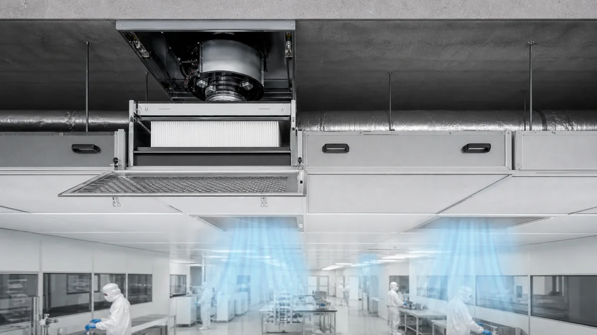
An FFU, or fan filter unit, moves air through a high-efficiency particle filter and delivers it near the cleanroom or clean zone. Stable performance requires three things to agree: the filter specification, the airflow delivered at the installed resistance, and the route that air follows through the occupied space. Choosing a higher filter grade does not, by itself, correct an inadequate return path or establish a room's particle classification.
Keep filter grade, airflow and room class separate
A HEPA or ULPA rating describes a filter tested under a specified method and condition. It does not describe every possible installed leak, nor does it classify the entire room. ISO 14644-1 classifies air cleanliness by airborne particle concentration at defined sampling locations. The process, occupancy, particle generation and installed system all influence that result.
An FFU may support a mixed-air room or form part of a unidirectional clean zone. The distinction depends on coverage, air distribution, returns and obstructions, not simply on having a ceiling full of fans. A local critical zone also needs clean air to reach the exposed work without first passing over a contamination source.

Select an operating point, not two catalogue maximums
The fan must deliver the required air volume against the resistance it actually encounters. State the airflow in m³/h or another consistent volume unit, the external static pressure in Pa, the fitted filter and the control setting. Check which losses are included in the supplier's rating. Maximum free-air volume and maximum static pressure are not normally available at the same operating point.
Allow for the resistance of a serviceable, loaded filter. A unit that only achieves the design flow with a new filter and the fan at its limit has little adjustment reserve. Conversely, selecting the largest fan without checking the required duty may add unnecessary noise or energy use. Compare power and sound data at equivalent airflow and resistance, with the measurement conditions stated.
Speed control, constant-flow control and remote status reporting are different functions. A network connection does not prove that a controller measures or maintains airflow. Confirm which variables are sensed, what an alarm means and how loss of communication affects operation.
Give the supply air somewhere useful to go
Coordinate FFU positions with lights, partitions, tall machines and return openings. A cabinet placed in front of a return can change circulation after commissioning. Closely located supply and return openings may allow air to leave before sweeping the intended work area. An acceptable average filter-face velocity can also hide low-flow patches, so use an appropriate measurement grid rather than one reading at the center.
Use the symptom to choose the next check
| Observed condition | Useful first checks |
|---|---|
| Air volume declines over time | Filter resistance, prefilter condition, inlet restrictions, fan command and available speed reserve. |
| Mean velocity is acceptable but a work area is poorly swept | Local velocity distribution, return locations, equipment obstructions and airflow visualization under representative use. |
| Particle counts rise while airflow appears unchanged | Installed filter and perimeter integrity, new particle sources, door events, cleaning and operating changes. |
These are investigation routes, not diagnoses. A pressure reading cannot prove filter integrity, and a clean filter-face reading cannot prove that an operator's working position is protected.
Agree on separate acceptance evidence
The handover plan should identify the room state, airflow measurements, relevant visualization, installed-filter leakage checks and particle-classification measurements. ISO 14644-3 provides supporting performance test methods; the selected tests and acceptance limits must match the application. Preserve the baseline measurements so later filter changes or layout alterations can be assessed meaningfully.
When comparing FFU configurations, include filter replacement direction, ceiling support, safe service access and controls. Specify the matching filter and sealing arrangement at the same time; external dimensions alone do not establish replacement compatibility.