


A dynamic pass box is a material-transfer enclosure that uses powered, filtered airflow and controlled door operation to move items between rooms. Its purpose is to manage the transfer environment while reducing the need for personnel to cross the room boundary. Effective operation depends on the load, airflow path, door sequence and cleaning procedure working together.
For a buyer, the important question is how the unit handles the actual transfer. A chamber that works well empty may behave differently when filled with tall containers, bags or instrument trays. Define the material route before choosing the enclosure.
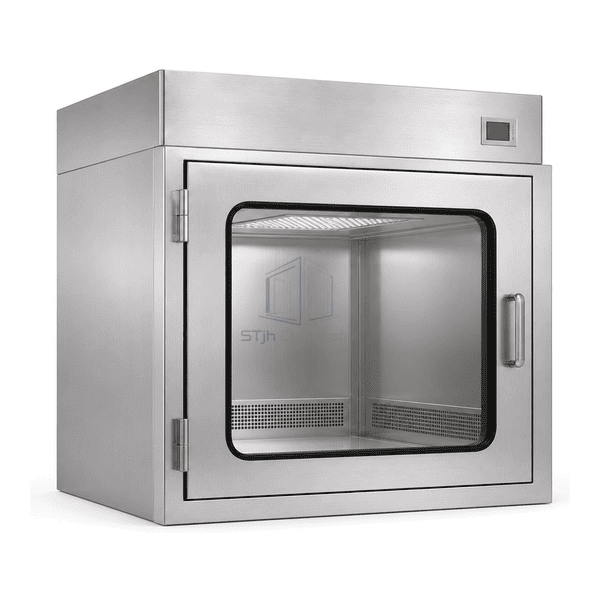
What happens inside a dynamic pass box?
A fan or connected air supply moves air through the filtration system and across the transfer chamber. Depending on the design, air can return to the filter circuit or leave through a defined path. These arrangements have different effects on the adjacent rooms. Ask for an airflow diagram that identifies the supply, return, discharge and any connection to building ventilation.
The filter captures particles from air passing through it. The EPA explanation of HEPA filtration describes this mechanical particle-removal function. It does not establish a particular pass box's installed performance. Filter seals, housing joints and airflow distribution also matter.
Filtered air alone does not establish that every transferred surface is clean or sterile. Packaging folds, contact areas and enclosed components need their own suitable handling and cleaning controls. Keep the equipment's air-cleaning function separate from the process requirements for the material.
Dynamic, static and containment transfer: different jobs
| Transfer approach | Main function | Important decision |
|---|---|---|
| Static pass box | Provides an enclosed, controlled transfer opening without powered chamber filtration | Whether the materials and room arrangement need active filtered airflow |
| Dynamic pass box | Adds powered filtered airflow to the transfer enclosure | Airflow path, loading arrangement, operating sequence and service access |
| Containment or treatment system | Addresses a specifically defined hazard or treatment process | Required containment direction, exhaust, process performance and safe handling |
A conventional dynamic unit should not be selected as protection for hazardous powders, biological agents or solvent vapors simply because it contains a HEPA filter. The hazard assessment and equipment design must address those duties specifically. Likewise, a material air shower and a filtered transfer chamber should be compared by their operating principles rather than treated as interchangeable names.
Make the transfer sequence visible to both operators
A useful operating sequence assigns a clear state to each stage. The exact controls depend on the chosen unit, so the procedure must follow its approved operating instructions.
Ready: Confirm the chamber is clear, required airflow is available, the opposite door is closed and no unresolved alarm is active.
Load: Prepare the external packaging as required by the site procedure. Place the material within the agreed loading area without obstructing supply or return openings.
Close: Check that the loading door is fully seated. A door resting against the frame is not necessarily correctly latched.
Airflow stage: Run the configured cycle or continuous-flow transfer sequence. Use the defined completion condition rather than an operator's estimate.
Unload: Release the receiving door only when the specified conditions are satisfied. Remove items without reaching back into the opposite room.
Reset: Check for debris, spills or damaged packaging and restore the chamber for the next transfer.
Both sides should understand the difference between busy, ready and fault indications. Where a process requires batch identification, record the material reference and any interrupted cycle rather than relying on a green light alone.
Specify what the interlock must do
The door interlock controls access; its presence alone does not demonstrate an airtight seal or correct airflow. Write down which conditions prevent a door from opening, what starts a cycle and what permits release. If airflow status is intended to control release, specify the relevant measurement and response rather than assuming a running fan proves adequate flow.
Discuss power failure, an open-door signal, a failed sensor and a stopped fan. The required response must balance material protection, operator safety and the facility's operating procedures. Emergency access and maintenance release need clear instructions. Operators should not bypass the interlock to overcome an alarm or shorten a transfer.
Set the load envelope before setting the cycle
List the largest item, its packaging, the number transferred together and the way it rests in the chamber. Check whether an operator can place and retrieve it without dragging it over a gasket or striking the filter guard. Door swing clearance outside the chamber is just as important as internal dimensions.
Use a loading drawing to show permitted positions and keep-out areas. Tall cartons can obstruct a supply face; stacked trays can create sheltered spaces; flexible bags can move toward return grilles. Changes to packaging or batch size should prompt a review of the loading arrangement and transfer procedure.
There is no universal purge time suitable for every chamber and load. Establish the operating conditions and acceptance criteria for the selected design and intended duty. ISO 14644-3 describes test methods for cleanrooms and clean zones, with methods selected for the relevant airflow and operating state. It should not be treated as an automatic guarantee of cleanliness for the transferred product.
Read the airflow, pressure and door signals together
Filter differential pressure measures the resistance between two pressure taps across the filter. Chamber-to-room pressure measures the pressure difference across the enclosure boundary. Label both readings by their measurement points: two instruments displaying pascals can be describing different parts of the system. A high filter-pressure reading does not, by itself, establish the direction of air movement through an open transfer door.
| Observed condition | Checks that separate the causes | Action before releasing transfers |
|---|---|---|
| Airflow falls after a larger load is introduced | Compare the loaded arrangement with the established layout; inspect supply and return clearances | Restore the permitted load position and repeat the operating check before changing fan settings |
| Airflow falls and filter pressure rises at comparable operating conditions | Check prefilter condition, filter resistance and the control setting against the recorded baseline | Service the restricted component and verify airflow; do not select a replacement from pressure alone |
| Fan is running but measured airflow is low | Check speed command, actual fan operation, obstructions and the measurement method | Resolve the fault instead of treating the fan-running indicator as an airflow result |
| A door-closed signal is present but the gasket has a visible gap | Check door alignment, latch engagement, gasket seating and contact-switch position | Repair the mechanical seal and then recheck the position signal; adjusting the switch alone does not close the gap |
| Receiving door remains locked after the timer ends | Read the active fault and release conditions, including opposite-door and airflow inputs | Find the unsatisfied condition; do not bypass the interlock to clear a normal transfer |
Compare measurements with the same door positions, fan setting, filter condition and load arrangement. Otherwise a change in operating state can be mistaken for a component failure. Keep troubleshooting access separate from normal operator access, and isolate electrical equipment before physical servicing.
Turn the acceptance plan into a usable handover record
Ask for a chamber drawing with load limits and clearances, an airflow diagram and a door-control sequence before manufacture. At handover, use the actual packaging and load arrangement rather than demonstrating only an empty chamber.
| Handover item | What to demonstrate or record |
|---|---|
| Loading and retrieval | The largest agreed package passes through the clear opening and can be retrieved without contacting seals or blocking airflow paths |
| Door sequence | Requests, door-position indication, release conditions and the response to a held-open door follow the agreed sequence |
| Airflow performance | Measurement positions, operating state, load layout, instrument and acceptance results are recorded together |
| Fault response | Qualified personnel demonstrate the specified response to loss of power and airflow using the approved test method |
| Maintenance access | Filter, seal and control-service access is available with the unit installed in its final wall opening |
These records provide a baseline for investigation after filter replacement, changes in packaging or alterations to the adjacent rooms. Define which changes require another performance check as part of the site's transfer procedure.
Install for cleaning and filter service
Agree the wall opening, support, finished wall thickness and sealing detail before fabrication. Keep controls reachable and service panels accessible. A filter that can only be removed through an obstructed ceiling or fixed cabinet creates avoidable maintenance work.
For routine care, inspect door seals, chamber corners and return openings. Use compatible cleaning materials and prevent liquid from entering electrical parts. Follow the equipment instructions for isolation before maintenance. Filter replacement should include checks appropriate to the installed system, rather than simply replacing the media and immediately releasing materials.
Build a practical zhengfeng enquiry
Start with the zhengfeng HEPA-filtered dynamic pass box and the material-transfer equipment range. Send the largest load dimensions, packaging type, wall arrangement, transfer direction, adjacent room conditions and expected transfer frequency. Include the required cleaning method and available service access.
Ask zhengfeng to propose the chamber layout, airflow arrangement and door-control sequence for that duty. Comparing these items together produces a more useful quotation than selecting a chamber size first and deciding how to operate it afterward.
Frequently asked questions
Does a dynamic pass box sterilize materials?
Powered filtration controls airborne particles passing through the filter. Sterilization requires a separately defined and demonstrated process; it cannot be inferred from the term dynamic pass box.
Can the chamber be filled completely?
Only the agreed load arrangement should be used. Filling the available volume can obstruct airflow, block access or prevent doors from sealing. Define clearances around the actual payload.
Is a timer enough to confirm that a transfer is ready?
A timer shows elapsed time. It does not independently prove adequate airflow, correct loading or acceptable particle conditions. Define the release conditions and checks for the selected system.