
 日本語
 ポルトガル語
 スペイン語
 マレー語
 インドネシア語
 ドイツ人。
 トルコ語
 ベトナム語
 フランス語で
 ロシア語
 アラビア語:アラビア語
 タイ語
 日本語で。流れ
 韓国語


FFU およびターミナル空気浄化装置
高気流ファンフィルターユニット
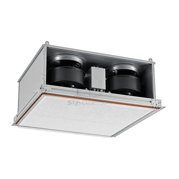
A large-format FFU with two EC blowers and a broad final-filter face, bringing a twin-fan clean-air supply assembly into one reinforced ceiling housing.
- Twin EC Blower Arrangement
- Large-Format Ceiling Housing
- Broad Final-Filter Face
- Common Control Enclosure
商品紹介
The high-airflow fan filter unit combines two EC blowers with a broad final-filter face in a reinforced ceiling housing. A central enclosure serves the twin-fan assembly, and the wide filter frame provides the outlet area for clean-air distribution. The large-format arrangement is intended for clean-air zones in which total delivered volume and the spatial distribution of that air must be considered together.
主要な特徴
The final-filter face extends beneath both blower positions.
A central enclosure brings the two blower connections together above the outlet assembly.
A reinforced perimeter supports the wide filter and diffuser assembly.
アプリケーションのソリューション
A high total airflow figure is only useful when the outlet pattern, control zoning and service requirements suit the work area.
One large module and several smaller modules create different control and maintenance layouts.Compare independent zones, electrical connections, ceiling coverage and replacement access before choosing the footprint.
A total volume figure does not show whether air reaches the far edges of a wide outlet.Define a multi-point velocity check across the effective filter face, including the areas beneath each blower.
A wide filter assembly needs space for removal as well as installation.Allow a clear service route and a safe lifting method for the complete filter and diffuser assembly.
Equal motor speeds do not by themselves establish equal airflow from the two fan zones.Evaluate the installed outlet pattern and use the specified control adjustment method when balancing the module.
典型的な用途
High-coverage semiconductor clean zonesLarge laminar-flow work areasBattery and precision-component productionCleanrooms with limited ceiling-module positionsHigh-air-change process rooms
技術的なパラメータ
Common reference configuration choices for a large-format, twin-blower FFU.
| Blower Arrangement | Two EC blowers within a shared ceiling housing |
|---|---|
| Large-Format Module | Common nominal format: 4 x 4 ft |
| Metric Housing Footprint | Typical metric-family option: 1175 x 1175 mm |
| 参照面速度 | Typical selection target: 0.45 m/s over the final-filter face |
| 住宅建設 | Reinforced metal casing with a broad final-filter support frame |
| Final-Filter Choices | Large-face HEPA or ULPA panel configuration |
| Supply-Voltage Option | Common option: 230 V AC |
| Control Assembly | Common electrical enclosure serving the twin-blower arrangement |
| Speed-Reference Options | Local adjustment or 0-10 V analogue reference; remote grouping with a compatible controller |
| Filter-Seal Construction | Perimeter gasket compressed against the final-filter frame |
| カスタマイズ | 意図したアプリケーションと動作環境に基づいて利用できます。 |
利用可能なオプション
Alternative large-format housing layoutsHEPA or ULPA final-filter selectionLocal speed adjustmentCompatible remote or group-control configuration
Air-Volume Selection and Installation
Size by delivered volume and usable outlet area
State the required total airflow in m³/h, the external resistance and the final-filter configuration. Use the effective open filter face when relating volume to average velocity; nominal housing area is not the same as usable outlet area. Room air-change calculations also require the room volume and the complete supply-and-return layout.
Choose the footprint and service arrangement
Provide the ceiling opening, supporting grid, available headroom and the route for lifting and replacing the filter assembly. Select the filter grade and sealing arrangement with the unit. Local adjustment and remote control are separate configuration choices; the supplied control system determines how the two blowers are adjusted and monitored.
Balance both fan zones
During commissioning, check total delivery and the velocity pattern at several positions beneath the filter rather than only at the centre. Match the circuit to the supplied electrical rating, secure the wide housing on its specified supports and isolate power before servicing either blower.
For resistance-led selections, compare the high-static-pressure fan filter unit. For smaller independently controlled ceiling zones, review the EC fan filter unit.
Planning a High-Airflow Fan Filter Unit specification?
寸法、設置条件、性能目標、必要な表面仕上げをお送りください。