
 EnglishCurrent
 葡萄牙语
 西班牙语
 马来语
 印尼语
 德语
 土耳其语
 越南语
 法语
 俄语
 阿拉伯语
 泰语
 日语
 韩语


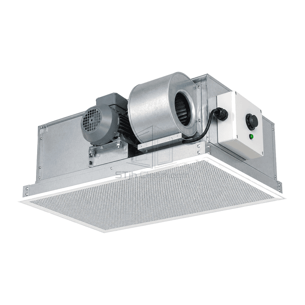
FFU and Terminal Air Purification Equipment
AC Fan Filter Unit
A ceiling FFU built around a permanent-split-capacitor AC motor and local speed adjustment for individually balanced clean-air supply.
- PSC AC Motor Configuration
- Local Airflow Adjustment
- Conventional Mains Supply
- Replaceable Final Filter
Product Introduction
The AC fan filter unit uses a permanent-split-capacitor induction motor to drive a centrifugal blower above a replaceable final filter. A local rotary controller provides individual speed adjustment, and a separate terminal enclosure keeps mains connections outside the filter interface. This version is intended for installations that use direct local adjustment rather than a networked control system. The wheel type, electrical variant and filter-replacement arrangement are selected for the installation.
Key Features
Local speed adjustment allows individual modules to be trimmed during airflow balancing.
A separate terminal enclosure provides a defined area for mains wiring.
The removable filter frame separates filter replacement from the motor assembly.
Solutions for Your Application
A locally controlled AC module suits a different operating strategy from a digitally managed FFU array.
Individual bays need different airflow settings.Use local adjustment and measure each installed module at the required operating point.
An unsuitable speed controller causes poor motor operation.Select the controller together with the PSC motor and capacitor rather than applying a general-purpose lighting dimmer or an unmatched drive.
Changed filter resistance alters the delivered airflow.Recheck the air volume during filter service and adjust within the motor/controller operating limits.
Maintenance parts are difficult to identify after installation.Record the motor, capacitor, controller and filter references with the supplied unit so replacements can be matched to the original configuration.
Typical Applications
Small independent cleanroomsRetrofit ceiling bays with local controlsCompounding support areasLaboratory clean benches and enclosuresFacilities standardizing on conventional AC maintenance parts
Technical Parameters
Reference ceiling sizes and supply variants for a locally adjustable PSC-motor FFU.
| Drive Type | Permanent-split-capacitor AC induction motor |
|---|---|
| Common Ceiling Module Formats | Nominal 600 × 600 mm and 600 × 1200 mm; imperial 2 × 2 ft and 2 × 4 ft versions |
| Typical Assembly Depth | Approximately 250–330 mm for conventional AC ceiling modules |
| Common Electrical Variants | 115 V AC, 60 Hz; or 220–240 V AC, 50/60 Hz; single-phase versions |
| Airflow Control | Local rotary fan-speed adjustment |
| Blower Arrangement | Centrifugal blower mounted above the filter plenum |
| Housing Material | Galvanized-steel plenum and service panels |
| Electrical Connection | Single-phase mains connection in a separate terminal enclosure |
| Final Filtration | Replaceable high-efficiency particulate filter |
| Filter Options | HEPA; ULPA configuration optional |
| Mounting and Sealing | Ceiling-grid flange, perimeter gasket and compression-sealed removable filter frame |
| Control and Service Options | Unit-mounted or wall-mounted control; bench-top or room-side filter replacement arrangement |
| Customization | Available based on the intended application and operating environment. |
Available Options
Electrical variant matched to the site mainsForward-curved or backward-curved blower configurationUnit-mounted or wall-mounted speed controlBench-top or room-side filter replacement
Choose the electrical and service configuration for the supplied unit; alternative variants are not interchangeable without checking compatibility.
Selection and Installation
Choose the electrical variant
Provide the site voltage, frequency and phase, the preferred controller location and the required power-connection method. The PSC motor, run capacitor and speed controller must be a compatible set. A list of possible voltages does not mean a single unit accepts every mains supply.
Compare operation at the required resistance
Request airflow, input power and sound data for the selected filter and fan setting, including the resistance used for the test. Local speed adjustment is not the same as automatic constant-airflow regulation; filter loading and upstream pressure changes can require rebalancing. If scheduled networking or automatic operating modes are needed, compare the EC fan filter unit and its actual control configuration.
Specify options before the ceiling is closed
The described version uses a locally adjusted AC drive. Select the wheel arrangement, final-filter grade, housing finish, controller position and replacement-filter route in the quotation. Confirm the module envelope, grid opening, support arrangement and clearance for the electrical box and service work. Room-side filter replacement does not imply room-side access to the motor or capacitor.
Keep service practical and safe
Locate the controller where airflow can be adjusted without disturbing the filter seal. After installation, measure the delivered air rather than using controller dial position as a flow reading. Electrical service requires isolation of the mains and safe handling of the motor capacitor by qualified personnel. After a filter change, inspect the frame seal and recheck the installed airflow. This supply module does not by itself provide biological containment, process sterilization or a room cleanliness classification.
Planning a AC Fan Filter Unit specification?
Send us your dimensions, installation conditions, performance targets and required surface finish.