
 EnglishCurrent
 葡萄牙语
 西班牙语
 马来语
 印尼语
 德语
 土耳其语
 越南语
 法语
 俄语
 阿拉伯语
 泰语
 日语
 韩语


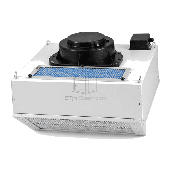
FFU and Terminal Air Purification Equipment
Standard Fan Filter Unit
A self-contained ceiling module for particle-controlled supply air, with an intake prefilter, blower and replaceable final filter.
- Integrated Blower and Final Filter
- Modular Ceiling-Grid Format
- Intake Prefiltration
- Top-Side Fan Access
Product Introduction
The standard fan filter unit packages a backward-curved centrifugal blower, shallow pressure plenum, mini-pleat final filter and perforated diffuser in one ceiling-mounted housing. Air enters through the top prefilter, passes through the distribution plenum and final filter, and leaves through the downstream face. A perimeter flange and gasket form the interface with the supporting grid. The fan is serviced from above; the final-filter replacement route depends on the selected filter-release configuration.
Key Features
Internal baffles distribute air across the mini-pleat pack instead of concentrating velocity directly below the fan inlet.
The perforated downstream face protects the filter media and moderates the outlet air pattern.
A gasketed ceiling flange limits bypass between the FFU frame and the supporting grid.
Solutions for Your Application
Selecting a standard FFU involves the ceiling interface, airflow balance and access to consumable filters.
Air reaches the filter unevenly from the fan outlet.The distribution plenum and baffle spread the incoming air; face measurements during balancing check the installed result.
A poor ceiling fit leaves gaps around the module.Match the flange and gasket to the grid bearing surface, then inspect the perimeter seal after the module is seated.
Prefilter dust loading reduces the airflow available to the clean zone.Keep the removable intake prefilter accessible for inspection and service, and recheck airflow when it is cleaned or replaced.
Final-filter replacement is difficult in a closed ceiling void.Choose the filter-release arrangement before ordering; clean-side release is an option rather than a feature of every module.
Typical Applications
Pharmaceutical cleanroom ceilingsElectronics assembly clean zonesMedical-device production suitesLaboratory preparation roomsModular hardwall and softwall cleanrooms
Technical Parameters
Common grid formats and configurable electrical and filtration choices complement the standard ceiling-module construction below.
| Common Nominal Ceiling Formats | 600 × 600 mm and 600 × 1200 mm grid modules |
|---|---|
| Typical Overall Depth | Approximately 230–320 mm for conventional ceiling FFU configurations |
| Housing Construction | Galvanized steel with a white epoxy-polyester powder coating |
| Blower Type | Backward-curved centrifugal blower |
| Filtration Arrangement | Removable intake prefilter and glass-fibre mini-pleat final filter |
| Final Filter Options | H13 or H14 HEPA; U15 ULPA configuration optional |
| Common Power Supply Options | 220–240 V AC, single phase; 50 Hz or 60 Hz electrical variants |
| Air Outlet | Perforated downstream diffuser |
| Ceiling Mounting and Sealing | Drop-in T-grid flange with a continuous perimeter gasket and sealed filter-to-housing interface |
| Control Options | Individual fan-speed adjustment or group-control connection |
| Service Access | Top-side fan access; clean-side filter release available as an option |
| Customization | Available based on the intended application and operating environment. |
Available Options
Square or rectangular ceiling-module formatApplication-selected final-filter gradeClean-side filter-release arrangementIndividual speed adjustment or group-control connection
List the selected module dimensions, filter and controls in the quotation so the supplied configuration is clear.
Selection and Installation
Size the ceiling bay and service space
Send the ceiling-grid opening, support detail, available plenum height and intended access route. Identify whether the unit draws from a common plenum or connects to ductwork. The module envelope, flange bearing and prefilter access need to suit the actual ceiling, not just its nominal grid size.
Specify the operating point
State the required airflow and available inlet conditions, together with the selected final filter. Request input power and sound data at that same duty point; motor nameplate power is not a substitute for operating consumption. For comparison within the range, review the locally controlled AC FFU and EC-motor FFU without assuming that this standard version uses either drive.
Identify what is included
The described module contains the housing, blower, intake prefilter, final filter and diffuser. Specify the required supply voltage, phase and frequency, final-filter grade, controller and cable connection in the enquiry. Group interfaces and clean-side filter release are choices, not implied standard equipment.
Plan balancing and maintenance
Match the fan-control method to any upstream airflow control. Measure supply airflow after installation and after changes to the filter or fan setting. Keep the top fan and prefilter service route clear; choose clean-side filter release where overhead access is impractical. Isolate electrical power before servicing, protect filter media from handling damage and verify the replacement filter seal before returning the area to use. The FFU is a room air-supply component, not a complete ventilation or containment system.
Planning a Standard Fan Filter Unit specification?
Send us your dimensions, installation conditions, performance targets and required surface finish.