
 영어
 포르투갈어
 스페인어
 말레이어
 인도네시아어
 독일어
 터키어
 베트남어
 프랑스어
 러시아어
 아랍어
 태국어
 일본어
 한국어현재 Current


FFU 및 터미널 공기 정화 장비
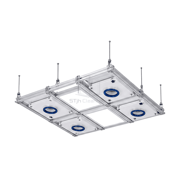
FFU 천장 그리드 시스템
A modular support-and-sealing framework that coordinates fan filter units, lighting, infill panels and service openings in the cleanroom ceiling.
- Coordinated Module Layout
- Gasketed Component Seats
- Demountable Grid Connections
- Suspension and Perimeter Options
상품 소개
The FFU ceiling grid system forms a repeatable framework for locating fan filter units, lights and blank panels above a controlled room. Main runners, cross members and matched intersections provide the module seats, while suspension and perimeter details connect the ceiling to its supporting structure. Gaskets and sealed interfaces address the boundary between the ceiling components. The grid is a coordination and support system, not the filtration equipment itself.
주요 기능
Matched intersections help control alignment across adjoining ceiling bays.
Gasketed bearing surfaces separate sealing from bare metal-to-metal contact.
Demountable components offer an alternative to cutting a fixed ceiling when a bay changes.
응용 프로그램 솔루션
A service-dense ceiling works best when geometry, loading and maintenance are designed together.
Nominal module sizes do not match the available opening.Coordinate the clear bay, support ledge and component flange instead of using nominal pitch as the only fit check.
Lighting and services compete with the required filter coverage.Allocate module and utility positions on one ceiling plan before assigning the FFU locations.
Gaps remain around drop-in components and penetrations.Provide continuous compatible sealing at the seats and purpose-made closures at joints and service openings.
Later equipment changes concentrate weight on an isolated runner.Assess the revised loads and support path before relocating components or adding suspended services.
일반적인 응용 프로그램
Semiconductor ballroom ceilingsModular pharmaceutical cleanrooms의료기기 생산 제품군Aerospace assembly clean zonesResearch laboratory cleanrooms
기술 매개변수
Common reference configuration choices for aluminium profiles, module pitches, seals and suspension hardware.
| Common Profile Material | Extruded aluminium alloy 6063-T5 |
|---|---|
| Common Visible Grid Width | 55 mm profile face |
| Common Profile Height | 70 mm section height |
| Common Metric Bay Pitches | 600 x 1200 mm or 1200 x 1200 mm |
| Common Surface Options | Clear anodized aluminium or white powder-coated finish |
| Component Sealing | Compressible gasket at the module-bearing interface |
| Grid Connections | Matched splice, tee, cross and corner connectors |
| Suspension Arrangement | Threaded steel rods and levelling hardware connected to the supporting structure |
| Module Types | FFU, lighting, blank infill and coordinated utility components |
| 사용자 정의 | 의도된 응용 프로그램 및 운영 환경에 따라 사용할 수 있습니다. |
사용 가능한 옵션
Metric or separately dimensioned imperial bay layoutAnodized or powder-coated profilesTop-access or compatible room-side service designFFU, lighting, infill and utility-bay arrangements
Choose connectors, suspension hardware, perimeter members and sealing components as one compatible system. Walkable construction requires a separately specified structural design.
Selection and Installation
Separate bay pitch from clear opening
Choose the ceiling module plan around the actual FFU and lighting envelopes, bearing flanges and removal routes. A 600 x 1200 mm bay pitch is a grid reference, not a guaranteed clear opening or a promise that every nominal 2 x 4 ft module will fit. Compare the selected fan filter unit flange and seal positions with the grid section before ordering.
Define the load path independently
Include the weights of filters, fans, lights, infill panels and any supported services, with the applicable concentrated and maintenance loads. The suspension arrangement, runner span, intersections, perimeter support and building anchors form one structural system. Do not assume a ceiling is walkable or can suspend process equipment because a similar-looking manufacturer's grid has a published load rating.
Specify how modules will be replaced
Select top-side insertion or a compatible room-side removable-flange arrangement before the layout is fixed. An independent bay does not automatically provide downward removal of every module. Leave the service space needed for wiring, duct connections, filters and safe handling without overloading neighboring members.
Close the sealing interfaces
Coordinate the module-seat gasket, splice joints, ceiling perimeter and service penetrations. Keep the sealing surfaces clean and use materials compatible with the intended cleaning regime. A gasketed seat helps form the boundary, but pressure tightness and room performance depend on the completed ceiling rather than the profile alone.
Planning a FFU Ceiling Grid System specification?
치수, 설치 조건, 성능 목표 및 필요한 표면 마감을 보내십시오.