 日本語
 ポルトガル語
 スペイン語
 マレー語
 インドネシア語
 ドイツ人。
 トルコ語
 ベトナム語
 フランス語で
 ロシア語
 アラビア語:アラビア語
 タイ語
 日本語で。流れ
 韓国語
Reduced-height packaging
The shallow module format addresses ceiling layouts limited by beams, existing services or equipment envelopes.



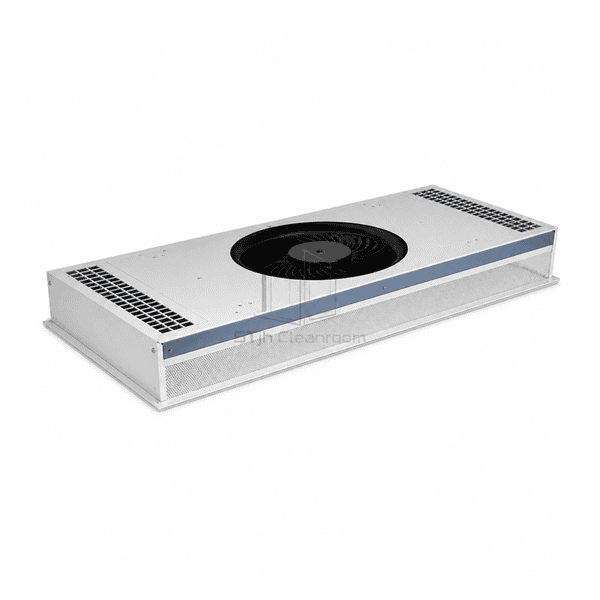
The low-profile fan filter unit packages the blower and final filtration stage in a shallow module for overhead installations. Its purpose is to fit clean-air delivery into a restricted space without selecting a conventional deep housing by default. The usable installation envelope depends on the complete assembly, inlet clearance and service route, while the filter area and air-distribution layout remain important to the finished airflow pattern.
The shallow module format addresses ceiling layouts limited by beams, existing services or equipment envelopes.
A rectangular final-filter face distributes supply air across an area rather than through a small open blower outlet.
The fan and final-filter stages are grouped in one installation footprint for ceiling or equipment integration.
Restricted headroom creates practical installation and maintenance problems that cannot be resolved by a housing-height figure alone.
Typical shallow-module dimensions and configuration choices for installations with limited overhead space.
| モジュールタイプ | Low-profile fan filter unit |
|---|---|
| Assembly Layout | Blower and final-filter section combined within a reduced-height module |
| Common Ceiling Format | Nominal 600 × 1200 mm or 2 × 4 ft format; equipment-specific footprints optional |
| Typical Complete Unit Height | Approximately 180–230 mm including the final-filter assembly in shallow configurations |
| 住宅オプション | Aluminium, powder-coated steel or stainless steel |
| Drive Options | AC or electronically commutated motor versions |
| Common Supply Options | 220–240 V AC, single phase, with 50 Hz or 60 Hz variants |
| ろ过ステージ | Final-filter assembly for particle removal |
| Filter Options | H13/H14 HEPA; compatible U15 ULPA configurations optional |
| Control Options | Local speed adjustment; remote analog or network controller configurations optional |
| Installation Application | Cleanroom ceiling voids and equipment spaces with restricted overhead height |
| カスタマイズ | 意図したアプリケーションと動作環境に基づいて利用できます。 |
Discuss the module footprint, final-filter arrangement, controller location and service side for the available space. Inlet collars and other accessories can increase the installed height. Filter replacement from the room and remote control equipment are separate configuration choices, not automatic features of a low-profile unit.
Record the available ceiling-void height and opening, then compare them with the unit's overall length, width and height in mm. Include the filter, mounting flange, projecting motor or controls, inlet accessories, cable bend space and the required free inlet clearance. A shallow casing is not the same as the minimum safe installation height. Check the support load and the removal route before the ceiling is closed.
Specify airflow in m³/h at the actual external resistance in Pa, including the final filter and any connected inlet or return-air restrictions. Review air distribution across the filter face as well as total airflow. Reducing internal height can affect distribution and pressure capability, so a taller unit's fan curve or outlet-velocity result must not be applied to a low-profile model. Compare the high-static-pressure fan filter unit where resistance, rather than available height, is the controlling requirement.
Specify separately how the filter, blower and electrical controls can be accessed. Room-side filter replacement does not necessarily make the motor or controller room-side serviceable. Allow enough space to lower the filter without damaging its face or seal, and retain access to the isolator and electrical connectors. Route cables clear of the inlet and removable parts.
Select the drive type, supply, speed adjustment and alarm functions independently of the low-profile housing. Obtain rated voltage, frequency, current, power in W and noise in dB(A) at the selected airflow duty. List the final-filter specification, control equipment, duct collar and any room-side service hardware in the quotation; a reduced-height unit does not automatically include these features.
寸法、設置条件、性能目標、必要な表面仕上げをお送りください。