
 日本語
 ポルトガル語
 スペイン語
 マレー語
 インドネシア語
 ドイツ人。
 トルコ語
 ベトナム語
 フランス語で
 ロシア語
 アラビア語:アラビア語
 タイ語
 日本語で。流れ
 韓国語


商品紹介
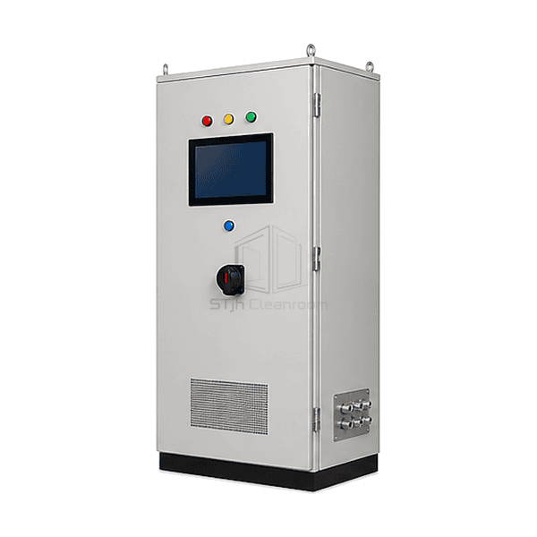
The FFU central control system brings the operator interface, network interfaces and control power components into a cabinet serving more than one cleanroom zone. Its screen layout can organize field units by room or process area, while compatible local fan electronics carry out the selected operating commands. This separates daily supervision from the individual FFU electrical assembly. The controller hardware, available feedback and software functions are selected together; a PLC, environmental sensors or historical database is included only when part of that architecture.
主要な特徴
Logical groups allow operators to select the intended area before applying an operating command.
A defined point list distinguishes commands, actual feedback and communications health.
Building-system integration can be selected without assuming that every field point should be remotely writable.
アプリケーションのソリューション
Central supervision is most valuable when its room map and command rules match the way the site is operated.
Operators cannot easily identify which FFUs serve a production area.Organize the screen and address schedule around named rooms, zones and equipment locations.
Local and building-system commands overwrite each other.Define control ownership and override priority instead of leaving several interfaces to issue conflicting instructions.
A lost network connection looks like a healthy stopped fan.Keep communication state separate from the commanded state and the feedback available from the drive.
Expansion adds devices that the original software cannot interpret.Choose an extensible address and interface plan using the actual control-card protocol and supported point definitions.
典型的な用途
Large semiconductor FFU ceilingsMulti-room pharmaceutical facilitiesBattery dry-room clean zonesDisplay and optics manufacturingCentral cleanroom operations centres
技術的なパラメータ
Common reference configuration choices for central FFU supervision.
| Control Level | Individual FFU, room-group and multi-zone supervisory commands |
|---|---|
| オペレーターインターフェース | Cabinet-mounted touchscreen HMI with a configured zone overview |
| Common HMI Supply | 24 VDC industrial-display configuration |
| Common Field Network | RS-485 with Modbus RTU for compatible addressed FFU control cards |
| Supervisory Interface Options | Modbus RTU, Modbus TCP over Ethernet, or a selected BACnet controller/gateway arrangement |
| Available Feedback Points | Run state, drive fault and communication status; speed feedback where provided by the fan electronics |
| Optional Operating Functions | Zone presets, schedules and alarm-event history in the selected software package |
| Enclosure Arrangement | Floor-standing or wall-mounted cabinet with segregated power and signal wiring |
| カスタマイズ | 意図したアプリケーションと動作環境に基づいて利用できます。 |
利用可能なオプション
Room-map or list-based HMI layoutAlarm-event history and selected trend pointsModbus or BACnet integration packageAdditional process-sensor inputs
Specify the required functions as a coordinated control package. An alarm-history option is not automatically a validated data-integrity system, and a process sensor is not supplied by the FFU network alone.
Selection and Installation
Build the control hierarchy around the facility
List the rooms, FFU addresses and operators who need access. Separate a system-wide command from a room command and from a maintenance override. If only one local zone needs coordination, compare the FFU group control panel before specifying a facility-wide supervisory cabinet.
Specify the actual interface at each boundary
Identify the fan-control card, supported protocol, register map and firmware at the field side. At the building system, define whether the connection is read-only monitoring or also permits writes, and assign command priority. An RS-485 terminal, Ethernet socket or BACnet label alone does not establish compatibility or expose the required points.
Keep electrical supply separate from signal definitions
The 24 VDC reference concerns an industrial HMI/control-electronics option, not fan-motor power or cabinet incoming mains. Size the cabinet supply, protective devices and field circuits for the actual equipment. A 0-10 V command is a signal interface; it must not be treated as a power supply or connected directly to a mains-speed controller.
Test loss and recovery behavior
Define what each FFU does after communication loss, controller restart and power restoration. Demonstrate group mapping, stale-data indication, alarm acknowledgement and the return from a local override. Schedules and setback levels should follow the facility's operating requirements rather than an assumed energy-saving percentage. A displayed speed value is not an independent airflow or particle-count measurement.
Planning a FFU Central Control System specification?
寸法、設置条件、性能目標、必要な表面仕上げをお送りください。