 İngilizce
 Almanca
 Arapça
 Fransızca
 Endonezya dilinde
 Japonca
 Korece
 Malay dilinde
 Portekizce
 Rusça
Rusça İspanyolca
 Taylandca
 TürkçeCurrent
 Vietnamca
Airflow and structure selected together
The perforation pattern determines the open route through the panel, while the supporting steel geometry determines how equipment loads reach the floor understructure.



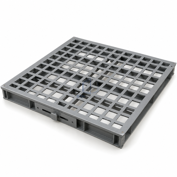
The AF38 configuration uses a powder-coated welded tubular steel body with a selected ventilation pattern providing up to 38% free cross-section. Panel thickness ranges from 30 to 38 mm within the reference family. Its purpose is to pair airflow geometry with an appropriate support and reinforcement selection, rather than treating every perforated steel panel as structurally interchangeable.
The perforation pattern determines the open route through the panel, while the supporting steel geometry determines how equipment loads reach the floor understructure.
An underside regulating arrangement can tune local airflow. Keep it accessible for commissioning and later adjustments when equipment density or operating heat output changes.
Standard and reinforced constructions serve different duties. Select the appropriate variant from the actual point loads instead of applying the highest family rating to every panel.
| Panel Grid | 600 x 600 mm |
|---|---|
| Thickness Range | 30–38 mm |
| Structure | Welded tubular steel |
| Surface Protection | Powder coating |
| Free Cross-Section | Up to 38% |
| Standard Point-Load Selection | 3–5 kN, depending on construction |
| Reinforcement | Higher-load variants available |
| Flow Regulation | Optional underside adjustment |
| Support | Matched pedestal and support system |
| Customization (Özelleşme) | Kullanılan uygulama ve çalışma ortamına göre kullanılabilir. |
Suitable for technical plant rooms, server suites and controlled equipment areas requiring ventilation through a raised floor. Define the actual loads and available air pressure together. Published airflow ranges describe different configurations and operating conditions; they should not be treated as a fixed output from an unpowered floor panel.
Choose the necessary reinforcement and support arrangement alongside the ventilation pattern for each loaded location.
Adjust the regulating arrangement and check the pressure and obstruction conditions beneath the panel after equipment changes.
Choose perforation pattern, supported load variant and suitable surface covering. Specify flow regulation where local adjustment is useful, and preserve access to the underside device without disturbing permanent equipment supports.
Bize boyutlarınızı, montaj koşullarınızı, performans hedeflerinizi ve gerekli yüzey kaplamalarınızı gönderin.