
 İngilizce
 Portekizce
 İspanyolca
 Malay dilinde
 Endonezya dilinde
 Almanca
 TürkçeCurrent
 Vietnamca
 Fransızca
 Rusça
 Arapça
 Taylandca
 Japonca
 Korece


Temiz Oda Hava Dağıtım Sistemleri
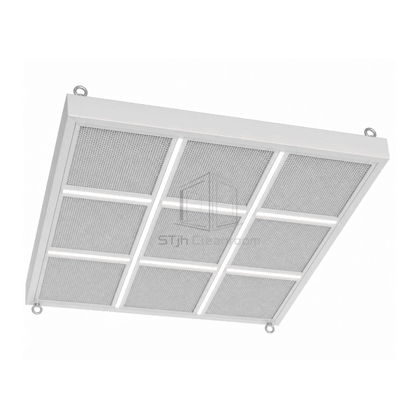
Temiz Oda Laminar Flow Tavanı
A modular ceiling assembly for terminal HEPA filtration and downward air supply across a defined clean process area.
- Terminal HEPA Filtration
- Broad Downward Air Supply
- Modular Plenum Assembly
- Diffuser and Lighting Options
Ürün tanıtımı
The cleanroom laminar flow ceiling combines a sealed supply plenum, multiple terminal HEPA filters and a perforated or textile diffuser surface above the process area. Its modular sections form a ceiling-level air-distribution assembly connected to an upstream air-handling system. Filter-cell joints, module connections and perimeter seals are part of the construction. The layout can incorporate lighting bays and service openings while reserving access to the filters and diffuser sections.
Ana Özellikler
Perforated and textile discharge surfaces offer different diffuser construction choices.
Sectional frames provide defined joints for assembly and perimeter sealing.
Lighting bays and service cutouts can be incorporated into the selected ceiling layout.
Uygulamanız için çözümler
A large clean-air ceiling must fit the work area and remain accessible throughout its service life.
Lights and equipment supports compete with filter space.Map obstructions before selecting the active supply footprint and the locations of blank or service bays.
Unequal inlet pressure can produce different discharge velocities across the array.Match duct connections and balancing provisions to the module layout, then measure the installed airflow rather than relying on a single inlet reading.
A filter replacement route is blocked by suspended equipment.Choose diffuser section sizes and a filter-release arrangement that remain accessible in the completed room.
Unsealed penetrations create bypass paths around the final filters.Include continuous perimeter seals and sealed service interfaces in the installation scope.
Tipik uygulamalar
Sterile pharmaceutical filling zonesHastane ameliyat odalarıAseptic product assemblyOpen process protection in biotechnologyPrecision microelectronics work areas
Teknik parametreler
Common ceiling-canopy formats and construction options for a duct-supplied clean-air zone.
| Montaj tipi | Modular ceiling plenum with an array of terminal HEPA filter cells |
|---|---|
| Common Nominal Coverage Formats | 1800 × 2400 mm or 2400 × 2400 mm; larger coverage assembled in modular sections |
| Typical Plenum Assembly Depth | Approximately 400–450 mm for conventional duct-fed canopy configurations |
| Filtre seçenekleri | H13 or H14 HEPA filter configurations |
| Air Supply Arrangement | Duct-fed pressure plenum supplying downward airflow through the filter and diffuser assembly |
| Diffuser Options | Perforated metal face or tensioned textile surface |
| Housing Finish Options | White powder-coated steel or brushed stainless steel |
| Air Supply Connection Options | Rectangular side-entry duct spigots with single or multiple supply connections |
| Module Connections | Bolted, gasketed sections with sealed perimeter and service interfaces |
| Filter Seal Options | Gel-seal or gasket-seal filter interfaces |
| Service Integration Options | Sealed lighting modules and planned openings for ceiling-mounted equipment |
| Customization (Özelleşme) | Kullanılan uygulama ve çalışma ortamına göre kullanılabilir. |
Mevcut Seçenekler
Perforated metal or tensioned textile diffuserSealed lighting baysGel-seal or gasket-seal filter interfacePerimeter skirts and equipment-service openings
Include each required accessory in the quotation; these items are not implied by the base ceiling description.
Selection and Installation
Define the protected footprint
For an enquiry, provide the process or operating-table layout, the required clean-air footprint, ceiling height and available installation depth. Include the positions of lights, pendants, rails and other obstructions. These details determine the module arrangement and accessible filter-replacement areas.
Match the ceiling to its air supply
State the required airflow, the target velocity and measurement plane, and the pressure available from the air-handling system. Select the filter grade, diffuser type and duct-inlet layout together. This duct-fed assembly needs a compatible upstream air supply; where integral fans are required, compare a ceiling fan filter unit.
Separate the assembly from optional accessories
The product described here is the plenum, terminal-filter and diffuser assembly. Identify the required material and filter seal in the quotation. Lighting, perimeter skirts, special service cutouts and monitoring accessories should be listed separately, along with the scope of ductwork and supporting steelwork.
Allow for servicing and room-level verification
Use the supplied installation drawing to locate supports and seal the ceiling perimeter and service penetrations. Leave space to remove diffuser sections and filters without contacting the filter media. After installation or filter replacement, check filter integrity and the airflow pattern in the completed room. Equipment, heat sources and room returns can disturb the downward field; the ceiling alone does not establish room classification or a sterile operating environment.
Planning a Cleanroom Laminar Flow Ceiling specification?
Bize boyutlarınızı, montaj koşullarınızı, performans hedeflerinizi ve gerekli yüzey kaplamalarınızı gönderin.