 Inglés
 El portugués
 EspañolCurrent
 El malayo
 Idioma indonesio
 Alemán
 El turco
 El vietnamita
 Francés
 El ruso
 El árabe
 Tailandés
 El japonés
 Coreano
Geometry follows the tool
Custom flange and outlet shapes let equipment designers place filtration beside the process rather than adapting the machine around a ceiling tile.



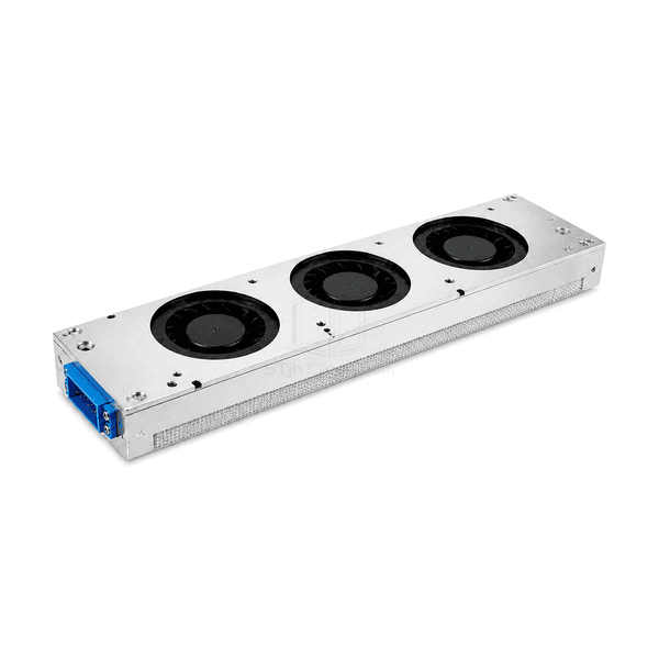
The equipment fan filter unit places the air-moving and final-filtration components inside or directly on a production tool. Its enclosure can follow a rectangular bay, an elongated opening or another defined machine interface rather than the grid of a room ceiling. The illustrated version uses a row of fans above a narrow filter face, with a flanged metal body and an end-mounted connector. Housing material, outlet direction, attachment holes and service access can be arranged around the equipment architecture.
Custom flange and outlet shapes let equipment designers place filtration beside the process rather than adapting the machine around a ceiling tile.
A planned hole pattern avoids drilling into the assembled filtration section during equipment installation.
Multiple fan positions can serve an elongated filter face where one central inlet would complicate the available space.
Power, command and fault connections can be arranged for the tool's wiring route and maintenance access.
Successful EFU integration depends on the space, return path and service needs of the individual machine.
Common component options and machine-interface details support selection of a narrow equipment module rather than a ceiling-grid FFU.
| Equipment Interface Format | Elongated rectangular module with a tool-specific length, width and flanged mounting pattern |
|---|---|
| Common Mini-Pleat Filter Depth Options | 30, 50 or 70 mm filter packs; overall module depth includes the separate fan chamber and mounting structure |
| Housing Material Options | Aluminium alloy, stainless steel or metallic-coated steel |
| Disposición de los ventiladores | Compact EC fan assembly; distributed-fan layout along the narrow outlet |
| Common Mains Supply Options | 220–240 V AC, single phase, with a 50 Hz or 60 Hz electrical variant |
| Final-Filter Options | Mini-pleat HEPA H13/H14 or process-selected ULPA filter |
| Interfaz de montaje | Bolted equipment flange with tool-specific hole pattern and perimeter gasket |
| Control Options | Local speed adjustment, analogue control or RS-485/Modbus interface with the matching controller |
| Configuración del servicio | Removable filter cassette and access direction arranged around the machine frame |
| Customization | Disponible según la aplicación prevista y el entorno operativo. |
Select the complete fan/filter stack and interface combination. A reduced housing depth does not mean every filter thickness or airflow duty fits the same envelope.
Define the required outlet area and the space available inside the process tool, including the actual opening, mounting datum, connector keep-out area and filter-removal direction. A long narrow strip, such as the illustrated arrangement, needs a different fan layout from a square module. Module depth must include the filter, fan, support flange and connector projection rather than only the bare fan housing.
Specify the usable outlet area, downstream obstructions and the path for displaced air to leave the enclosure. Air velocity at the filter face is not automatically the velocity at a wafer, camera or transport stage. Select the fan against the resistance of the complete tool airflow path, and review airflow uniformity, power and sound at the same operating point.
Choose the actual supply variant and identify which power conversion, controller and cables are included. An EC motor does not necessarily accept low-voltage DC at the equipment connector. Define pinout, enable signal, speed command, feedback and fault behavior together; a Modbus option needs the matching register map and communication settings.
Provide clearance to withdraw the filter without scraping media against the tool frame. Use the selected gasket compression and support method, and evaluate vibration at the machine mounting points rather than assuming a fan-type label guarantees stage stability. This clean-air module is not a solvent exhaust, dust collector or containment device. Where the task is room-level filtration rather than tool integration, compare the fan-powered HEPA ceiling module.
Envíenos sus dimensiones, condiciones de instalación, objetivos de rendimiento y acabado superficial requerido.