
 EnglishCurrent
 葡萄牙语
 西班牙语
 马来语
 印尼语
 德语
 土耳其语
 越南语
 法语
 俄语
 阿拉伯语
 泰语
 日语
 韩语


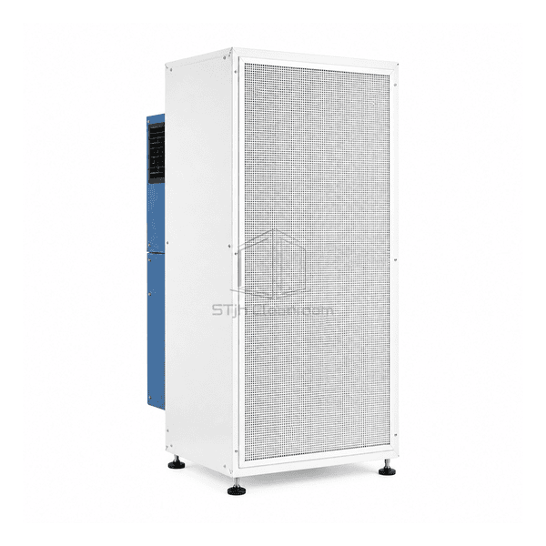
FFU and Terminal Air Purification Equipment
Side-Discharge Fan Filter Unit
A vertical fan filter cabinet that delivers clean-air supply horizontally at process level when an overhead module is unsuitable.
- Horizontal Supply Direction
- Vertical Cabinet Format
- Adjustable Levelling Feet
- Rear or Top Inlet Options
Product Introduction
The side-discharge fan filter unit turns the supply face into a vertical plane for horizontal delivery beside equipment or a work zone. Its upright cabinet places the fan compartment behind the final filter rather than above the process. A broad perforated front protects the discharge assembly, and levelling feet support the cabinet at floor level. Rear intake and top-connection arrangements offer different ways to integrate the module with surrounding services when ceiling-mounted supply is impractical.
Key Features
A vertical outlet provides a different equipment-layout option from downward ceiling supply.
Levelling feet allow the upright cabinet to be aligned on the supporting floor.
Rear service access keeps fan maintenance separate from the exposed process side.
Solutions for Your Application
Horizontal supply can solve a layout problem, but its position relative to the process determines whether it is useful.
Overhead equipment leaves no suitable ceiling bay.Place the supply cabinet beside the work zone and assess the clear path from the vertical filter face to the exposed product.
A machine blocks the path from an overhead module.Consider an outlet at working height, with equipment openings and process surfaces arranged to receive the lateral stream.
A wall-side installation obstructs the return-air inlet.Select a compatible intake position and preserve the inlet clearance instead of pushing the cabinet flush against the wall.
Servicing the unit would disturb nearby production equipment.Plan the rear access space, filter-removal route and any movement or restraint arrangement before the cabinet is installed.
Typical Applications
Low-clearance clean boothsPharmaceutical filling linesPrecision inspection stationsFood packaging zonesClean transfer corridors
Technical Parameters
Common reference configurations for process-level horizontal air supply.
| Cabinet and Air Direction | Upright cabinet supplying air horizontally through its vertical front filter face |
|---|---|
| Common Filter-Module Formats | Nominal 24 × 24 or 24 × 48 in modules, approximately 610 × 610 or 610 × 1220 mm |
| Typical Face-Velocity Setting | Approximately 0.45 m/s at the discharge filter face, with adjustable fan speed |
| Drive Configuration | Rear-mounted EC centrifugal fan with local speed adjustment |
| Common Electrical Options | 115–120 V AC, 60 Hz; or 220–240 V AC, 50/60 Hz, single-phase motor versions |
| Final-Filter Options | Mini-pleat HEPA or ULPA filter behind the protective outlet grille |
| Housing Material Options | Powder-coated steel or 304 stainless steel cabinet construction |
| Air-Inlet Options | Rear room-air intake or top duct-entry connection |
| Support Arrangement | Adjustable levelling feet with an application-specific restraint or mounting frame option |
| Service Arrangement | Rear fan compartment access and front-removable filter assembly |
| Customization | Available based on the intended application and operating environment. |
Available Options
Single- or twin-module supply arrangementRear intake or top duct connectionFixed feet or locking-caster supportHEPA or ULPA final-filter selection
Choose the module count, support method and filter-access route as a compatible assembly. Casters or mounting hardware are not included by implication.
Selection and Installation
Define the protected working plane
Provide the height, width and depth of the exposed process, the distance from the filter face and the positions of operators and equipment. Avoid placing a contamination source upstream of the product in the horizontal stream. A freestanding cabinet does not create an enclosed clean zone simply by being positioned beside a production line.
Preserve the inlet and discharge paths
Choose rear intake or a top connection to suit the actual return-air arrangement, and leave the specified inlet clearance. Plan where discharged air can leave the work zone without short-circuiting back to the intake. If an unobstructed ceiling route is available, compare the standard ceiling FFU rather than assuming horizontal flow is preferable for every process.
Select support and maintenance access together
State whether the cabinet will stand on feet, use casters or attach to an independent frame. Specify the required restraint for the cabinet and maintenance loads, and do not treat a filter frame as a structural wall anchor. Reserve rear access and a front withdrawal path for the selected filter; a narrow installation gap can otherwise make routine service impractical.
Check the installed air pattern
Request the selected assembly's air volume or face velocity, filter resistance, power and noise data, then check the actual work zone with the equipment in place. Horizontal supply is for product-side particle control, not hazardous-fume extraction or biological containment. A process requiring aseptic protection needs an appropriately designed and qualified complete environment, not a cleanliness claim inferred from the FFU alone.
Planning a Side-Discharge Fan Filter Unit specification?
Send us your dimensions, installation conditions, performance targets and required surface finish.