
 영어
 포르투갈어
 스페인어
 말레이어
 인도네시아어
 독일어
 터키어
 베트남어
 프랑스어
 러시아어
 아랍어
 태국어
 일본어
 한국어현재 Current


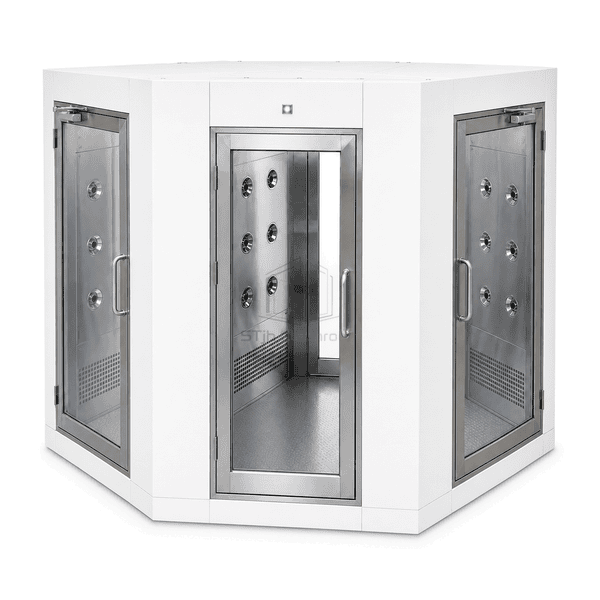
상품 소개
The three-door air shower introduces a third doorway to a common cleaning chamber. Its enclosure combines door frames, nozzle panels, return grilles and an accessible blower/filter section around the available wall area. In a destination-selective configuration, the controller coordinates the selected exit with the closed-door signals and cleaning cycle. This lets one gowning entrance serve two controlled zones or a T-shaped circulation plan without duplicating the whole shower enclosure.
주요 기능
Exit selection can be linked to the required destination path.
Centralised nozzle coverage serves the shared cleaning space.
Branch-aware status indication
Door and cycle signals can distinguish a selected destination from a busy or unavailable branch.
Layout-specific maintenance access
Removable panels allow service positions to be selected without reserving every chamber wall for equipment access.
응용 프로그램 솔루션
The extra doorway is useful when destination rules are as clear as the physical route.
One gowning room must feed two clean production areas.Two selectable clean-side doors can be connected to separate controlled routes.
Operators may choose the wrong exit.Destination selection can enable only the permitted clean-side door after cleaning.
Requests from two branches arrive during the same cycle.Use a defined priority or queue rule, retain the active destination until the sequence finishes and show the other route as unavailable.
Sharing the shower could transfer incompatible residues between rooms.Assess process compatibility and cleaning procedures; use separate equipment where a shared chamber cannot meet the separation requirement.
일반적인 응용 프로그램
Shared pharmaceutical gowning roomsLaboratory suites with two controlled wingsElectronics route separationCleanroom corridor junctions
기술 매개변수
The following are selectable three-door air-shower references, not a single tested STjh model schedule. Compact footprint and nominal door-width examples describe one published three-door family; other manufacturers corroborate the configuration but use different sizes.
| 문 배열 | Three controlled doorways around one personnel cleaning chamber |
|---|---|
| Typical Routing | One gowning entrance and two destination exits; left-hand or right-hand branch arrangement |
| Compact Footprint References | 1264 x 1372 mm or 1264 x 1829 mm, enclosure width x depth |
| Nominal Door Width Reference | 914 mm; actual clear passage depends on the selected frame and leaf |
| Housing Options | Powder-coated steel or Type 304 stainless steel |
| Filtration Arrangement | Return-air prefilters and a final HEPA filter in a recirculating air circuit |
| Cleaning Outlets | Adjustable wall nozzles with optional supplementary ceiling nozzles |
| Common Cycle-Timer Option | 0-99 s adjustable run-time range |
| Post-Cycle Wait Option | 0-10 s adjustable delay before normal exit release |
| Common Supply Option | 208 V AC, 60 Hz, three phase; alternative regional supplies available |
| Access-Control Options | Door-position monitoring, electronic interlocks and destination-selective release |
| Service Arrangement | Removable nozzle-wall or ceiling access panels, depending on blower and filter position |
| 사용자 정의 | 의도된 응용 프로그램 및 운영 환경에 따라 사용할 수 있습니다. |
사용 가능한 옵션
T-shaped or offset arrangementDestination card-reader inputSwing or sliding clean-side doorsRoute status indicatorsType 304 stainless enclosureSupplementary ceiling nozzlesRemote alarm and release interfaces
Common construction includes the shared recirculation chamber, filter stages and timed controller. Destination permissions, powered doors, special exit sequencing and external safety interfaces are separate selections. A card-reader input controls permission; it does not by itself define the door interlock or emergency behavior.
Selection and Installation
Define which rooms may share the chamber
Identify the gowning side, each destination and the permitted return paths. Two clean-side connections do not automatically make different processes compatible. Review garment policy, pressure relationships and contamination sensitivity before using one chamber for both rooms. A common air circuit does not provide independent containment between destinations.
Write a route-by-route door sequence
Choose how the destination is selected and which door becomes available after the cycle and any wait period. In a destination-selective arrangement, the unused branch remains closed during normal travel. Define what happens when another person requests the other route, a door does not reach its closed position or a cycle is interrupted. Do not assume every door may be opened together or used freely in both directions.
Separate routine access from emergency response
Normal interlocking and security permissions are different from emergency release. Select the actual manual-release, alarm and power-loss functions for all three openings, including their connection to the building's safety arrangements. The third door is not automatically a dedicated emergency exit, and a route-selection controller alone does not establish compliant evacuation.
Fit the whole three-door junction
Allow space for each door leaf, queue and destination corridor, plus the filter and blower service route. Nominal door width is not measured clear opening. Keep outlets and returns clear of door frames and users waiting at a branch. Choose occupancy from the usable chamber area and operating sequence, not the number of doors. If only one corner connection is needed, compare the L-shaped air shower; if entry and exit share one wall, compare the U-shaped return-route air shower.
Planning a Three-Door Cleanroom Air Shower specification?
치수, 설치 조건, 성능 목표 및 필요한 표면 마감을 보내십시오.