 영어
영어 독일어
독일어 아랍어
아랍어 프랑스어
프랑스어 인도네시아어
 일본어
일본어 한국어현재 Current
 말레이어
말레이어 포르투갈어
포르투갈어 러시아어
러시아어 스페인어
스페인어 태국어
태국어 터키어
터키어 베트남어
베트남어No intentional ventilation openings
The closed face suits locations where air should pass through designated neighbouring panels instead of directly beneath a process-tool footprint or equipment base.



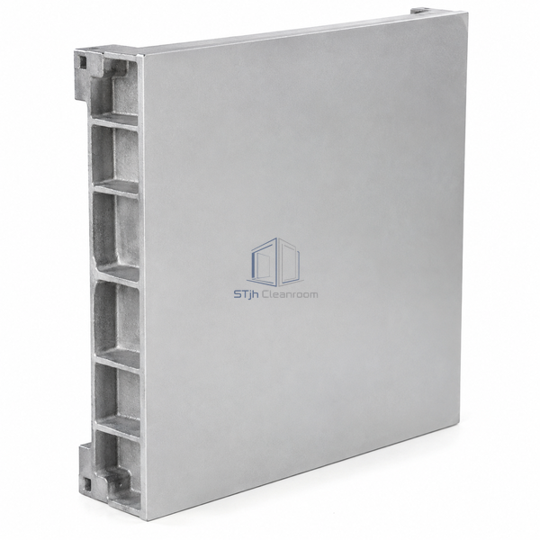
This 600 mm grid panel uses a solid die-cast aluminum body with orthotropic structural geometry beneath the walking face. The construction directs material into supporting ribs while keeping the top free from airflow perforations. It is selected for cleanroom equipment locations that need accessible underfloor services and a continuous floor surface, with panel thickness in the 52–60 mm reference range.
The closed face suits locations where air should pass through designated neighbouring panels instead of directly beneath a process-tool footprint or equipment base.
The cast support geometry provides a defined load path to the pedestal system. Equipment feet and service openings need to be considered against that structure.
Aluminum offers a non-magnetic panel body without a wood or cement-filled core. The selected surface finish should match cleaning and electrical requirements.
| Panel Grid | 600 x 600 mm |
|---|---|
| 패널 두께 | 52–60 mm |
| Panel Material | Die-cast aluminum |
| Structural Form | Orthotropic ribbed body |
| Top Geometry | Solid, unperforated |
| Reference System Weight | 27–42 kg/m² |
| Pedestal Height Range | 50–2,000 mm |
| Surface Options | Conductive coating or suitable resilient finish |
| Access Method | Individually removable modules |
| 사용자 정의 | 의도된 응용 프로그램 및 운영 환경에 따라 사용할 수 있습니다. |
Use around semiconductor tools and clean technical equipment where a solid floor is required alongside ventilating modules. The support structure, panel variant and tool load distribution determine the installation's usable capacity. Plan future service openings before manufacture so they do not remove critical rib sections or leave an unsupported panel edge.
Use the solid module there and concentrate airflow through separately selected ventilation panels in the room layout.
Match the panel and understructure to the actual foot positions and provide dedicated support where the tool layout requires it.
Select the panel depth, finish and support height. Coordinate electrical bonding and service penetrations with the equipment plan, and use compatible lifting tools to maintain the finished surface during access work.
치수, 설치 조건, 성능 목표 및 필요한 표면 마감을 보내십시오.