
 영어
 포르투갈어
 스페인어
 말레이어
 인도네시아어
 독일어
 터키어
 베트남어
 프랑스어
 러시아어
 아랍어
 태국어
 일본어
 한국어현재 Current


상품 소개
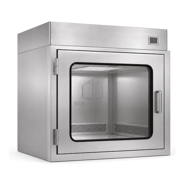
The dynamic pass box incorporates air-handling space around an enclosed stainless transfer chamber. Its upper fan/filter assembly supplies the chamber from above, and return openings near the base feed air back into the internal circuit. This recirculating arrangement addresses particles suspended during loading without requiring a dedicated building supply duct for the ordinary configuration. Doors, prefilter access and the final-filter housing are coordinated with the selected control sequence and maintenance side.
주요 기능
Distributed return openings avoid relying on a single small return point.
Filter-resistance indication supports maintenance trending between service visits.
Selectable fan control allows the circulation setting to suit the loaded chamber.
Door-delay functions can coordinate loading with the chosen air-cleaning cycle.
응용 프로그램 솔루션
Air cleaning must work with the load geometry and the way operators use the chamber.
Wrapping releases loose particles after material has been loaded.Use a defined loading practice and an internal filtered-air stage before the receiving-side transfer; remove unnecessary outer packaging separately.
A large carton blocks the lower air-return area.Choose chamber proportions and load positioning that preserve the return path instead of compensating with a longer timer alone.
The circulation setting drifts as the filters accumulate dust.Trend pressure drop alongside the actual airflow checks and service the appropriate filter stage before resetting the operating condition.
The receiving door is released after a disrupted loading sequence.Select control logic that handles an opened door or fan fault distinctly from a completed cycle, rather than treating every countdown as successful treatment.
일반적인 응용 프로그램
Prepared components entering medical-device assemblyWrapped supplies for biotechnology support roomsContainers for controlled packaging operationsParticle-sensitive electronics material transfer
The unit conditions chamber air; it does not sterilize material surfaces or remove chemical vapours. Sterile-process duties and hazardous-substance transfer require a separately supported transfer method rather than reliance on the HEPA element or interlocked doors alone.
기술 매개변수
These commonly offered dynamic-pass-box configurations are selectable references rather than a tested STjh operating schedule. Chamber size, fan selection, filter resistance and the load arrangement are considered together; no fixed airflow, recovery time, power or noise result is assigned here.
| Air Circuit | Integral fan-driven recirculation through the chamber filtration loop |
|---|---|
| Internal Size References | 500 × 500 × 500 or 600 × 600 × 600 mm, W × D × H |
| Chamber Lining Options | 304 stainless steel; 316L stainless steel selectable |
| Final Filter Selection | H14 HEPA element to EN 1822 |
| Prefiltration | Serviceable particle prefilter upstream of the final filter |
| Chamber Air Path | Upper filtered-air supply with low-level return grilles |
| 팬 배열 | Integrated centrifugal blower with selectable speed adjustment |
| Electrical Supply Reference | 230 V AC, single phase, 50 Hz configuration |
| 문 통제 | Two-door electronic interlock with selectable delay logic |
| 필터 모니터링 | Differential-pressure indication across the final filter |
| Operating Mode Options | Continuous circulation or a timed post-loading air cycle |
| Service Arrangement | Accessible filter housing and separate prefilter service provision |
| 사용자 정의 | 의도된 응용 프로그램 및 운영 환경에 따라 사용할 수 있습니다. |
사용 가능한 옵션
Variable-speed fan controlTimed circulation and access-delay functionsDigital or analogue filter-pressure displayHEPA test-access connectionsStainless outer casingWall or stand-supported installation
The usual starting arrangement combines an interlocked chamber, recirculation fan, prefilter and final filter. Display format, operating modes and service access are selected for the transfer route. A room-pressure display, when required, is a separate sensing function from pressure drop across the HEPA filter; neither a gauge nor a filter grade establishes a complete room classification.
Selection and Installation
Choose the usable chamber around the actual transfer load, leaving the ceiling outlet and low-level return openings unobstructed. Tall containers and tightly packed trays can redirect the air even when the fan is running. Establish the loading pattern and required particle-recovery behaviour before choosing the circulation setting or the receiving-door delay.
Filter pressure drop helps track loading but is not a direct measurement of filter leakage or chamber cleanliness. The selected controls should distinguish normal circulation, an interrupted cycle and a fan or door fault; an elapsed timer alone does not establish that goods are sterile or safe to release. For an existing wall where the installation and maintenance envelope are the main constraint, compare the self-contained HEPA pass box while retaining the same need to assess the loaded airflow path.
Planning a HEPA-Filtered Dynamic Pass Box specification?
치수, 설치 조건, 성능 목표 및 필요한 표면 마감을 보내십시오.