 EnglishCurrent
 葡萄牙语
 西班牙语
 马来语
 印尼语
 德语
 土耳其语
 越南语
 法语
 俄语
 阿拉伯语
 泰语
 日语
 韩语
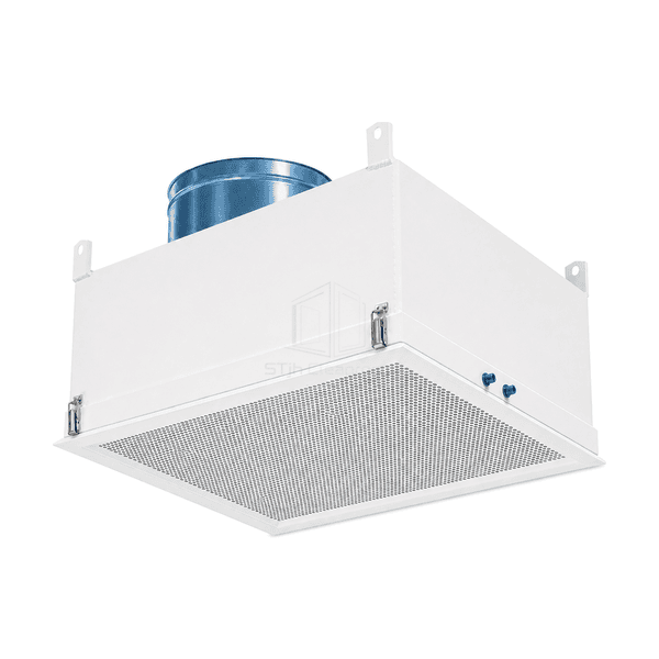
Cleanroom HEPA Terminal Housing
A reusable duct-connected housing for a replaceable final filter, with access from the room side and no internal fan.



Bring your fan filter units, controls and ceiling interfaces together. Explore central controls, group controllers and supporting components to manage clean-air zones and fit your installation requirements.
Start with the operating task and site constraints, then compare the product direction that best matches the intended use.
| Buyer requirement | Product direction | Why it helps |
|---|---|---|
| Ducted final-filter terminal | Cleanroom HEPA Terminal Housing | Connects a supply duct to a sealed room-side serviceable filter. |
| Complete ducted air terminal | Integrated HEPA Clean Air Supply Module | Combines damper, equalization plenum, final filter and diffuser. |
| Coordinated ceiling support | FFU Ceiling Grid System | Supports FFUs, lights, blanks and service modules in sealed bays. |
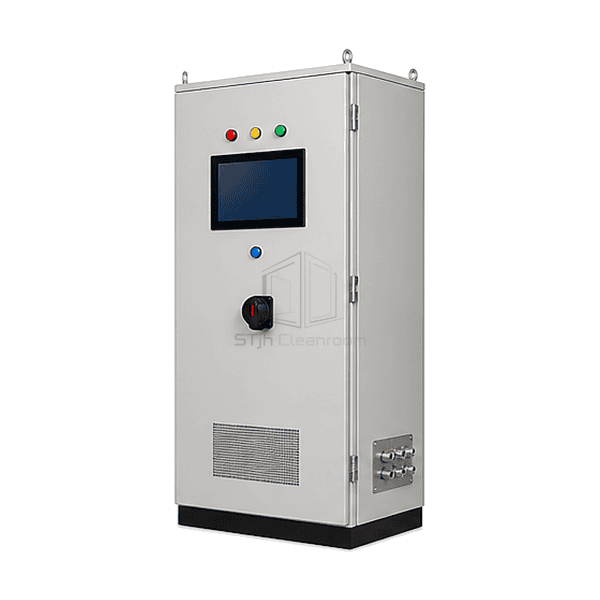
| Whole-room multi-zone supervision | FFU Central Control System | Provides HMI-based zone commands, alarms and network integration. |
| One-zone coordinated operation | FFU Group Control Panel | Controls a defined FFU group without a full central cabinet. |
| Single-unit adjustment or BMS integration | EC FFU Speed Controller or FFU BMS Communication Gateway | Provides local setpoint control or translates the FFU field bus for the building system. |
Narrow your choices by the features that matter to your application. View specifications and add suitable models to your inquiry list for a tailored quote.
A reusable duct-connected housing for a replaceable final filter, with access from the room side and no internal fan.
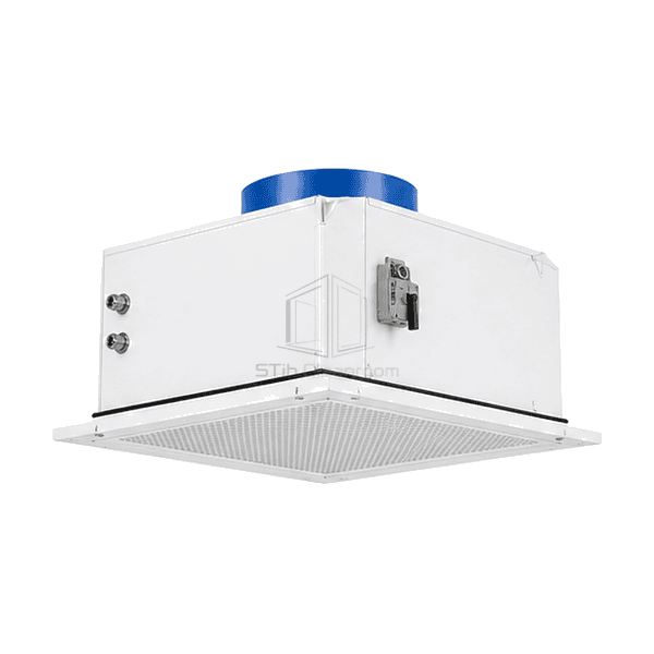
A coordinated ducted supply terminal bringing the plenum, final filter, balancing arrangement and room-side diffuser into one ceiling assembly.
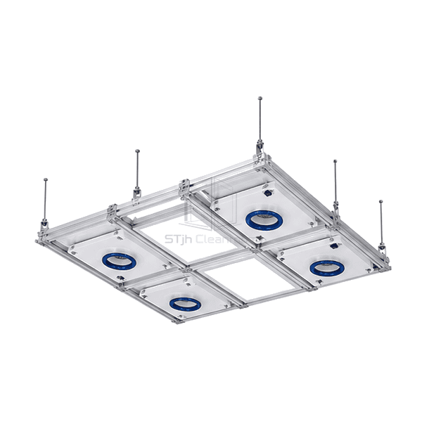
A modular support-and-sealing framework that coordinates fan filter units, lighting, infill panels and service openings in the cleanroom ceiling.
A cabinet-based supervisory system for organizing FFU commands and available feedback across multiple cleanroom zones.
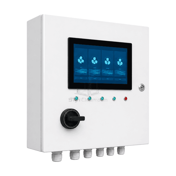
A local panel for coordinating a defined FFU group without requiring operators to use a facility-wide supervisory station.
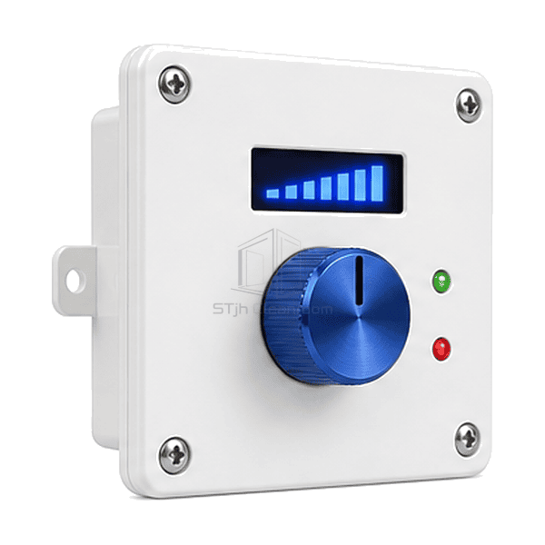
A room-side rotary interface for setting the command to a compatible EC fan filter unit without accessing the ceiling-mounted adjustment point.
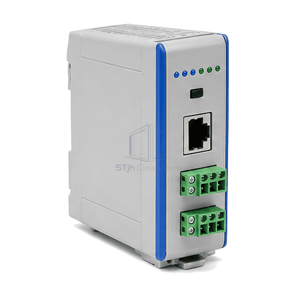
A DIN-rail interface for exchanging selected commands and operating data between compatible fan filter controls and the building management system.
Simplify the coordination of multiple FFUs with controls and ceiling components selected as a system. Match unit grouping, monitoring, building-management interfaces and service access to the way your cleanroom operates.
It is useful when multiple zones require coordinated commands, alarm visibility, operating schedules or building-network integration.
A compatible local controller can command one EC FFU using the supported low-voltage interface, subject to the motor and controller specifications.
It also coordinates module dimensions, seals, blank panels, lights and service penetrations, so it should be planned with the ceiling layout.
Confirm the FFU field protocol, gateway protocol, network topology, point list, addressing and responsibility for commissioning.
Share your FFU schedule, ceiling layout and control requirements. Ask our team to help you select compatible components and quote your system.