
 Inglés
 El portugués
 EspañolCurrent
 El malayo
 Idioma indonesio
 Alemán
 El turco
 El vietnamita
 Francés
 El ruso
 El árabe
 Tailandés
 El japonés
 Coreano


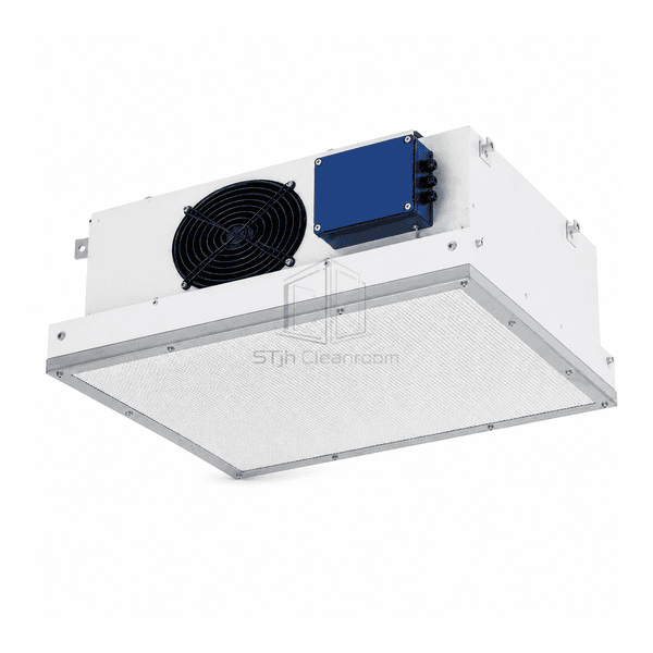
FFU y equipos de purificación de aire terminal
Unidad de filtro ULPA
A ceiling fan filter module for particle-sensitive processes, with the ULPA filter, perimeter seal and fan operating point selected as one assembly.
- ULPA Final-Filter Configuration
- Interfaz de filtro sellado
- Adjustable Fan Operation
- Filter-Access Options
Introducción del producto
The ULPA fan filter unit places a pleated final-filter panel below a fan plenum to supply filtered air into a ceiling bay or mini-environment. Its rigid housing supports the filter frame and separates the intake side from the discharge face. The described EC-driven version permits fan-speed adjustment, while the filter grade, perimeter-seal design and replacement route form separate configuration choices. This arrangement is intended for processes in which fine-particle contamination matters more than a general clean-air supply specification.
Características clave
The protected discharge face reduces direct handling of the pleated media.
A defined perimeter interface allows the seal to be inspected during filter replacement.
Separate fan and filter selections accommodate different clean-air supply duties.
Soluciones para su aplicación
A demanding particle specification needs attention to the complete air path, not just a higher filter designation.
Particles bypass the filter through an unsuitable perimeter joint.Match the filter and housing seal designs, inspect the seating surfaces and check installed leakage after assembly.
A replacement filter changes the resistance seen by the fan.Rebalance delivered airflow with the replacement panel fitted, rather than assuming the previous controller setting remains suitable.
A ceiling layout leaves insufficient room to withdraw the filter.Select the replacement side and reserve the panel-removal envelope before fitting adjacent services.
Uneven delivery leaves part of the process poorly supplied.Check the installed face-velocity distribution and the effect of nearby obstructions instead of treating a single center reading as the whole result.
Aplicaciones típicas
Fabricación de obleas de semiconductoresFabricación avanzada de pantallasAsamblea óptica de precisiónÁreas de investigación en nanotecnologíaMinientornos críticos
Parámetros técnicos
Common reference filter and drive choices for a ULPA ceiling supply module.
| Unit Arrangement | Self-contained ceiling fan module supplying air downward through a replaceable ULPA panel |
|---|---|
| ULPA Class Options | Common final-filter selections: U15 or U16 |
| Final-Filter Face Options | Common panel face sizes: 610 x 610 mm or 1220 x 610 mm |
| Velocidad superficial de referencia | Typical selection target: 0.45 m/s through the selected ULPA panel |
| Fan Configuration | Variable-speed EC centrifugal drive above the final-filter plenum |
| Supply-Voltage Option | Common option: 230 V AC |
| Control-Input Options | Local potentiometer or 0-10 V analogue speed reference; compatible network controller as an option |
| Construcción de viviendas | Rigid metal plenum with a coated exterior |
| Filter-Seal Options | Dry-gasket compression or a matched knife-edge and gel interface |
| Filter-Access Options | Top-side or room-side replacement |
| Customization | Disponible según la aplicación prevista y el entorno operativo. |
Opciones disponibles
ULPA final-filter grade selectionDry-gasket or gel-seal frameLocal or grouped fan controlAcceso al filtro del lado superior o de la habitación
Select the filter, drive interface and service arrangement together; alternative configurations are not standard equipment on every unit.
Selection and Installation
Select the filter assembly, not only its class
State the required ULPA class, filter face dimensions and acceptable pressure loss at the intended airflow. Match the replacement panel to its frame, seal channel and retaining arrangement. A ULPA label describes filter performance; it does not establish the installed room classification or replace inspection of the complete filter-to-housing interface.
Specify the complete operating point
For a comparable quotation, include required air volume or face velocity, upstream pressure, the selected filter resistance and the intended control range. Ask for airflow, input power and noise at the same operating condition. EC speed control alone does not demonstrate automatic constant airflow, and a speed setting is not an airflow measurement.
Provide a practical testing and service route
Choose gasket or gel sealing and top-side or room-side filter replacement before the ceiling layout is fixed. Allow space for safe panel removal and the selected in-place leak-test method. Filter access from below does not automatically provide access to the fan or electrical enclosure; include those service clearances separately.
Distinguish particles from process gases
If the process is sensitive to airborne molecular contaminants as well as particles, compare the AMC chemical filter FFU. A ULPA particle filter is not a substitute for target-specific molecular media or a hazardous-process exhaust system.
¿Planificación de una especificación de la Unidad de filtro de ventilador ULPA?
Envíenos sus dimensiones, condiciones de instalación, objetivos de rendimiento y acabado superficial requerido.