 Inglés
 El portugués
 EspañolCurrent
 El malayo
 Idioma indonesio
 Alemán
 El turco
 El vietnamita
 Francés
 El ruso
 El árabe
 Tailandés
 El japonés
 Coreano
Height-specific liquid application
Spray positions can be arranged around the hood, body and footwear instead of relying on a single overhead outlet.



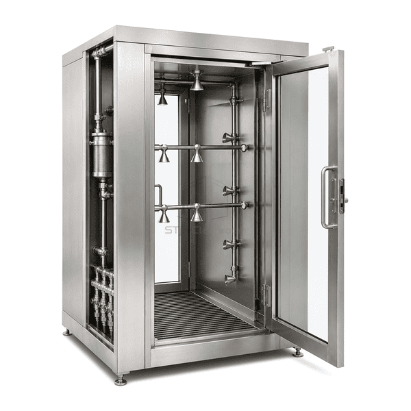
The low-flow wet-down shower uses water-spray headers at different heights inside a protective-clothing change chamber. Controlled spray intervals apply liquid to the suit exterior, with a subsequent holding stage before departure. The water circuit can incorporate an accessible strainer and flushable branches, while the stainless floor collection area receives runoff. Circuit zoning, nozzle selection and drain details are arranged around the garment and the intended transition between wet and dry changing areas.
Spray positions can be arranged around the hood, body and footwear instead of relying on a single overhead outlet.
Selected valve groups let the wetting sequence follow the intended garment task without continuous spraying between users.
An accessible strainer and suitable flushing points help manage debris that can distort a nozzle's spray.
A separate drip-hold stage gives the operator a planned pause above the collection area before leaving.
Controlled suit wetting depends on where liquid is applied, how long it runs and where the runoff goes.
Use is selected around the actual residue and protective clothing. Cytotoxic compounds, nanomaterials, water-reactive powders and other hazardous duties need a specifically supported exposure-control process; the wet-down chamber alone does not establish that suitability.
These selectable construction and circuit references apply to direct garment wetting, rather than a fine-mist cloud or emergency body wash. They are not measured STjh specifications. Total water demand depends on the selected nozzles, simultaneous spray circuits and spray-on time; the plan-size example is not a clear-chamber or doorway dimension.
| Wetted Surface Options | 304 o 316 acero inoxidable |
|---|---|
| Stainless Sheet Reference | 0.8–1.5 mm sheet for selected enclosure surfaces |
| Nominal Footprint Reference | Approximately 1300 × 1300 mm; other chamber sizes selectable |
| Spray Positions | Upper, middle and boot-level water-spray positions |
| Spray Circuit Control | Controlled spray-on intervals; independently valved zones selectable |
| Circuito de agua | Regulated liquid supply with a serviceable inlet strainer |
| Passage Layout | Two-door suit-change passage |
| Operating Stages | Programmable wetting and drip-hold sequence |
| Runoff Collection | Stainless drain tray or graded floor with a collection outlet |
| Piping Service Options | Branch flushing and residual-water drainage |
| Air-Handling Connections | Selected supply and exhaust connections; exhaust filtration optional |
| Customization | Disponible según la aplicación prevista y el entorno operativo. |
The starting arrangement is a controlled water-spray chamber with height-distributed outlets, stainless runoff collection and a planned post-spray hold. Individual valve groups, service functions and the wet-to-dry exit arrangement are selectable. Chamber size, materials and the operating sequence can be customized for the intended garment and process.
Specify the total operating liquid flow in L/min at the nozzle-manifold pressure, which circuits run together, and the spray duration. Include line flushing and chamber cleaning when estimating collected liquid per operating period. A small nozzle or a low pump setting alone does not establish reduced total consumption. Select the minimum suitable application for the actual garment-wetting task without treating it as a substitute for a required emergency body shower or eyewash.
Review the outer fabric, seams, cuffs, closures, footwear and any worn equipment for compatibility with the selected water quality and wetting method. Direct sprays deposit liquid differently from a fine-mist cloud; use the intended garment and wearer positions when choosing nozzle angle, distance and circuit timing. Wetting the outside does not demonstrate chemical neutralization, removal of all residue or protection against liquid reaching an unsuitable garment layer.
Size the inlet strainer for the selected nozzle passages and keep it accessible for cleaning. A strainer captures suspended particles; it does not remove dissolved hardness or guarantee that scale cannot form. Provide suitable branch flushing or drainage where needed, and compare actual spray flow and pressure with the selected nozzle data after servicing. Keep service work separate from an occupied cycle.
Match the tray, outlet and liquid-collection route to the residue carried by the suit. Set the post-spray hold and departure procedure around remaining drips rather than assuming a timer makes the suit dry. Maintain the selected ventilation and pressure strategy through the sequence, with an agreed door-release and emergency-egress response. If the task instead calls for fine droplets with less direct surface wetting, compare the personnel misting decontamination shower.
Envíenos sus dimensiones, condiciones de instalación, objetivos de rendimiento y acabado superficial requerido.