
 Inglés
 El portugués
 EspañolCurrent
 El malayo
 Idioma indonesio
 Alemán
 El turco
 El vietnamita
 Francés
 El ruso
 El árabe
 Tailandés
 El japonés
 Coreano


FFU y equipos de purificación de aire terminal
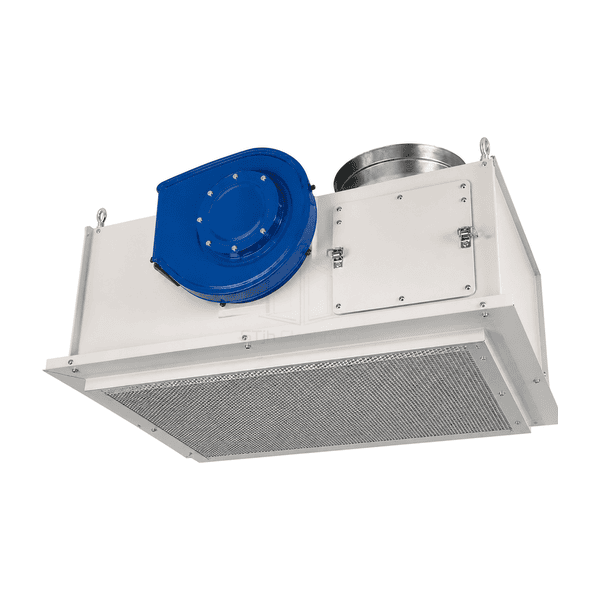
Unidad de filtro de soplador (BFU)
A ceiling supply assembly combining a centrifugal blower, a duct-entry housing and a downstream particulate filter in one module.
- Integrated Blower and Filter
- Duct-Entry Housing
- Perforated Outlet Guard
- Ceiling Supply Configuration
Introducción del producto
This blower filter unit combines an upper blower compartment with a lower final-filter section in a coated metal enclosure. A round collar provides the duct-entry interface, while the rectangular outlet guard covers the discharge face. The cabinet includes an upper access cover and a removable lower panel for the respective service areas. It is intended as a powered cleanroom supply terminal selected together with the air system it connects to.
Características clave
A defined duct-entry interface makes the upstream connection part of the module specification.
The upper fan chamber and lower filter section provide distinct component locations.
The lower outlet guard can be opened without using the upper access cover.
Soluciones para su aplicación
A powered terminal needs to be selected as part of the connected air circuit, not from the blower name alone.
Required supply volume changes when duct resistance is added.Match the blower curve to the installed duct and filter losses instead of using a free-air volume as the delivered duty.
Central supply pressure varies while the terminal fan is running.Choose a balancing and control arrangement that accounts for both fans across the intended operating range.
Filter replacement and motor repair need different access space.Plan both removal routes before selecting the terminal position and ceiling opening.
Two quotations use BFU and FFU for apparently similar equipment.Compare the actual housing, inlet, fan curve, filter seal and service arrangement rather than assuming the abbreviations define different performance levels.
Aplicaciones típicas
Duct-connected cleanroom supply pointsElectronics packaging areasClean assembly roomsCeiling supply in enclosed production zonesEngineered clean-booth air systems
Parámetros técnicos
Common reference construction and component options for a duct-connected blower-filter terminal.
| Assembly Arrangement | Upper centrifugal-blower section feeding a lower particulate-filter section |
|---|---|
| Reference Terminal-Module Formats | Nominal 24 × 24, 24 × 36 or 24 × 48 in families, approximately 610 × 610, 610 × 915 or 610 × 1220 mm |
| Housing Material Options | Coated-steel cabinet or 304 stainless steel, with a perforated lower outlet guard |
| Duct Inlet | Round entry collar on the upper housing, with a flanged connection option |
| Blower Choices | Forward- or backward-curved centrifugal wheel with a matching AC or EC motor |
| Particulate-Filter Options | HEPA or ULPA final filter with a gasketed or gel-seal interface |
| Common Single-Phase Supply Options | 120 V AC, 60 Hz, or 220–240 V AC, 50/60 Hz, depending on the motor version |
| Control Options | Local speed control; compatible EC versions with an external 0–10 V DC speed-reference input |
| Monitoring Accessories | Static-pressure tapping points and an optional filter-condition indicator |
| Acceso al servicio | Upper blower cover plus a removable lower outlet-panel and filter assembly |
| Customization | Disponible según la aplicación prevista y el entorno operativo. |
Opciones disponibles
Duct-entry size and positionFinal-filter grade and sealing interfaceFan motor and control arrangementUpper and lower maintenance access layout
Specify the supplied build as a complete assembly. A recirculating inlet, acoustic lining, room-side motor access or a network controller requires its own configuration and is not established by the BFU designation.
Selection and Installation
Define the complete duty point
Provide the required air volume and the pressure conditions at the inlet and outlet. Compare the selected blower curve with duct, damper and final-filter resistance, including the intended filter-loading allowance. BFU is a blower-filter name, not a pressure rating; it does not by itself establish greater capacity than an FFU.
Coordinate with the upstream air system
Identify whether the inlet connects to a ducted supply or a defined recirculation path. An upstream fan and a local blower affect one another, so their operating ranges and balancing method need to work together. This terminal assembly does not replace the central system's heating, cooling or humidity-control duties.
Specify two distinct maintenance routes
Plan access to the blower, motor and electrical components separately from final-filter removal. Check ceiling depth, opening size, support points, lifting route and the clearance needed to lower the filter assembly. Room-side filter access does not automatically mean that the motor can be serviced from the room.
Compare construction, not abbreviations
State the filter grade and seal, inlet interface, sound and power requirements, control function and replacement method in the equipment schedule. For a conventional grid-mounted comparison, see the standard fan filter unit. After installation, measure the air delivered to the room and check the filter seal; the BFU label alone does not guarantee a cleanliness class or a unidirectional working zone.
Planning a Blower Filter Unit (BFU) specification?
Envíenos sus dimensiones, condiciones de instalación, objetivos de rendimiento y acabado superficial requerido.