
 Inglês
 Portuguêsatual
 Espanhol
 Língua malaia
 Língua indonésia
 Alemão
 Língua turca
 Vietnã
 Francês
 Língua russa
 Língua árabe
 Tailandês
 Japonês
 Coreano


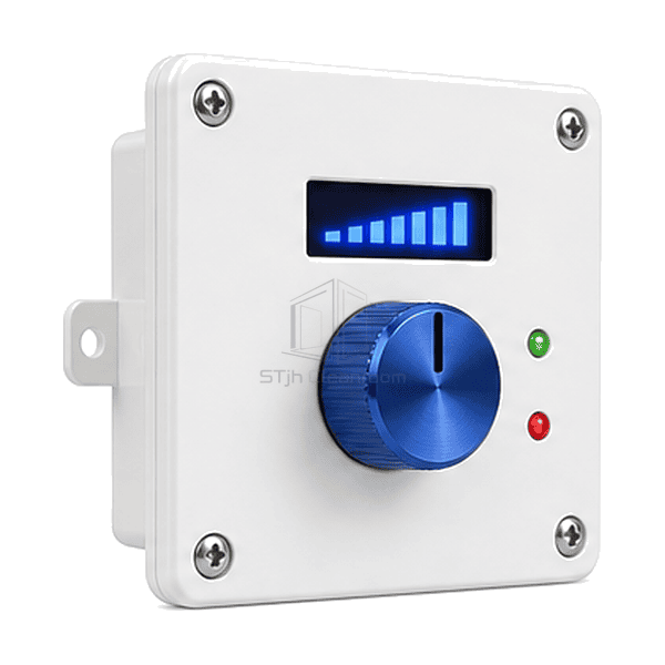
FFU e equipamento de purificação de ar terminal
Z Controlador de velocidade EC FFU
A room-side rotary interface for setting the command to a compatible EC fan filter unit without accessing the ceiling-mounted adjustment point.
- Local Rotary Adjustment
- 0-10 V Interface Option
- Optional Setpoint Display
- Surface or Flush Mount
Introdução do produto
The EC FFU speed controller places a rotary operating interface on the room side of an installation. The knob produces the selected speed reference for compatible fan electronics, with a display available for the command value or supported feedback. Its compact operator plate can be mounted independently of the FFU's mains enclosure. Analogue, powered-display and PWM arrangements use different circuits, so the controller version is chosen to match the actual motor rather than the EC label alone.
Características-chave
A simple rotary interface avoids a full supervisory screen for a standalone fan duty.
An optional indication makes the selected command easier to reproduce during setup.
Selected limit settings can restrict the available adjustment to the intended operating range.
Soluções para sua aplicação
A suitable local controller matches the electrical input and makes the useful setting clear to the operator.
The FFU's trim control cannot be reached during normal room operation.Provide a remote operating plate at an accessible location with the specified control cable.
The replacement controller has the right connector shape but the wrong function.Match the supply, signal reference and pin assignment to the motor documentation rather than to plug appearance.
A displayed setting is mistaken for measured clean-air delivery.Label the indication as command, voltage or supported RPM and use an airflow measurement when balancing the FFU.
Operators repeatedly move the setting outside the useful duty range.Select an appropriate limit-setting version and define the permitted range using the installed operating requirements.
Aplicações típicas
Single EC fan filter unitsClean benches and mini-environmentsIndependent ceiling FFU zonesEquipment fan filter modulesLaboratory clean-air stations
Parâmetros técnicos
Common reference specifications and selectable local EC control versions.
| Função de controle | Manual rotary speed-reference adjustment for a compatible EC input |
|---|---|
| Common Analogue Signal | 0-10 VDC command between signal output and the specified common reference |
| Common Reference Supply | 10 VDC fan-reference option for a matched potentiometer controller |
| Display Options | Command percentage or signal voltage; RPM indication with compatible feedback |
| Adjustment Options | Stepless rotary setpoint; minimum/maximum limits in the selected controller version |
| Alternative Interface | Motor-specific PWM version as a separate selection from analogue output |
| Installation Options | Surface enclosure or flush-mounted operator plate |
| Customização | Disponível com base na aplicação pretendida e no ambiente operacional. |
Opções disponíveis
Rotary-only or display-assisted operator interfaceAnalogue reference or matched PWM versionMinimum/maximum adjustment limitsSelected enable or feedback interface
A separate active circuit is needed for functions such as isolation, signal conversion or additional indications; these do not follow from a rotary potentiometer alone.
Selection and Installation
Identify the fan's control input
Use the exact motor/control-card reference to select analogue or PWM operation. Confirm the signal range, common reference and the behavior at zero command, minimum speed and signal loss. Do not select a lighting dimmer, AC voltage regulator or generic PWM power driver in place of the specified EC signal interface.
Keep reference power and command voltage distinct
A common potentiometer arrangement uses a fan-provided 10 VDC reference to produce an adjustable command. A display or active output circuit may need a different supply and more current. Do not connect two independent reference supplies together or assume that a fan's small auxiliary output can power every display controller. Mains isolation and motor protection remain separate from the speed-reference knob.
Read the display for what it actually represents
A percentage, bar graph or command-voltage value describes the selected setting. Actual motor RPM requires the appropriate feedback, and actual airflow requires its own measurement. Record the useful operating adjustment after balancing the installed FFU rather than using knob position as a flow calibration.
Choose a suitable operating location
Specify the plate or enclosure footprint, mounting depth, cleaning exposure and cable route before installation. Select remote enable, fault indication or galvanic isolation only where the chosen circuit provides them. If multiple fans require coordinated commands and status, compare the FFU group control panel instead of assuming the local controller can drive an arbitrary parallel group.
Planning a EC FFU Speed Controller specification?
Envie-nos as suas dimensões, condições de instalação, metas de desempenho e acabamento de superfície necessário.