 EnglishCurrent
 葡萄牙语
 西班牙语
 马来语
 印尼语
 德语
 土耳其语
 越南语
 法语
 俄语
 阿拉伯语
 泰语
 日语
 韩语
Metallic-coated exterior
The casing uses a coated steel surface rather than relying solely on a decorative paint film.



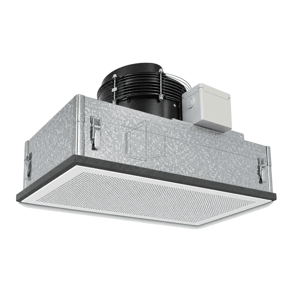
The Aluzinc-coated steel fan filter unit uses aluminium-zinc metallic-coated sheet for its formed casing and access cover. Folded edges shape the plenum around the fan and separate final-filter frame, while the natural spangled surface distinguishes the enclosure from a painted sheet or brushed stainless finish. Coating specification, exposed edges and fastener interfaces matter as much as the visible face when selecting this construction. The motor, controls and final filter are chosen separately from the enclosure material.
The casing uses a coated steel surface rather than relying solely on a decorative paint film.
Folded access edges and fastener positions allow the enclosure details to be specified for the installation.
Choose the drive and controller around the required operating point without confusing casing material with motor performance.
A separate filter frame allows the access route and sealing interface to be selected around maintenance needs.
A coated steel FFU should be selected for the environment in the ceiling void as well as the clean zone below it.
These are application examples for a metallic-coated enclosure, not approval for persistent condensation, chemical spray or washdown exposure.
Common reference casing and operating-configuration choices for an Aluzinc-coated FFU.
| Enclosure Substrate | Steel sheet with an aluminium-zinc metallic coating |
|---|---|
| Coating Family | Common alloy family: approximately 55% aluminium, with zinc and silicon |
| Casing Footprint | Typical rectangular option: 1175 x 575 mm |
| Exterior Finish | Natural metallic spangle |
| Sheet-Metal Construction | Formed and folded enclosure with a removable cover |
| Fan-Drive Options | AC motor or EC motor configuration |
| Electrical Option | Common supply option: 230 V AC |
| Reference Face Velocity | Typical FFU selection target: 0.45 m/s |
| Final-Filter Options | HEPA or ULPA panel with a separately matched support frame and seal |
| Outlet Construction | Perforated outlet grille below the final-filter frame |
| Maintenance Options | Upper-plenum or room-side filter service |
| Customization | Available based on the intended application and operating environment. |
The supplied combination should identify the controller, filter and enclosure finish together. Clean-side filter access does not imply clean-side motor removal or automatic airflow regulation.
Identify the base steel, metallic-coating designation and mass, surface treatment and exposed edge treatment in the material schedule. A visible spangle does not establish the coating composition or durability. Describe likely condensation, salt exposure and cleaning chemicals; aluminium-zinc coating must not be treated as a universal substitute for stainless steel in wet or chemically aggressive conditions.
Provide the target air volume and system resistance, then compare the selected fan/filter combination at that duty point. Obtain the supply voltage, frequency, phase, input power, controller arrangement and acoustic test conditions for the actual variant. AC and EC are alternatives, not proof of a particular network function or constant-flow control. The EC fan filter unit page explains the separate drive-selection considerations.
Use the defined lifting and support points, protect the coated sheet from dragging and remove cutting or drilling debris. The drawing should establish module dimensions, mass, flange engagement and the access needed around the top fan and terminal box. Do not drill additional suspension holes or attach dissimilar-metal hardware without the specified interface detail.
State whether filter replacement must take place from above the ceiling or from the room. Confirm the matching filter size, sealing profile and removal space; a hinged grille alone does not establish the complete replacement procedure. Keep the enclosure dry where practical and use a compatible surface-cleaning method without wetting the media or electrical components. After service, inspect the seal and measure installed airflow rather than relying on motor speed alone.
Send us your dimensions, installation conditions, performance targets and required surface finish.