Filled welded shell
The steel top and shaped bottom pan are welded into an assembly with internal cementitious material, distributing loads through the panel rather than an exposed board edge.

 Bahasa Inggeris
 Bahasa Jerman
 Bahasa Arab (Bahasa Melayu)
 Bahasa Perancis
 Bahasa Indonesia: Bahasa Indonesia
 Bahasa Jepun
 Bahasa Korea (Bahasa Melayu)
 Bahasa Melayu (Bahasa Melayu)Semasa
 Bahasa Portugis: Bahasa Portugis: Bahasa Portugis
 Bahasa Rusia
 Bahasa Sepanyol: Bahasa Sepanyol: Bahasa Sepanyol
 Bahasa Melayu (Bahasa Melayu)
 Bahasa Turki: Bahasa Turki
 Bahasa Vietnam (Bahasa Melayu)

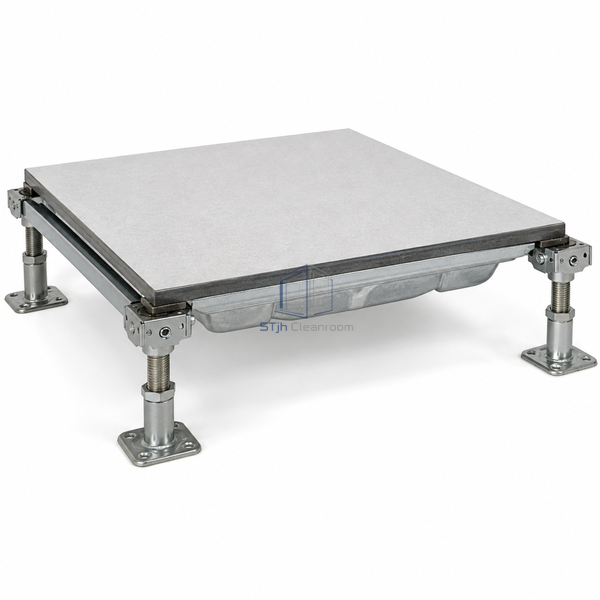
This configuration pairs a 24 x 24 inch welded steel panel with a cementitious core and a 4 ft bolted-stringer understructure. Its reference system duty is 1,500 lb design load, with 900 lb repeated rolling load at 10,000 passes. These values belong to the panel and support arrangement together. The mineral-filled shell offers a distinct construction from woodcore and die-cast aluminum modules.
The steel top and shaped bottom pan are welded into an assembly with internal cementitious material, distributing loads through the panel rather than an exposed board edge.
Bolted stringers connect the pedestal layout and support the selected system duty. Matching only the panel dimensions is insufficient when replacing existing floor components.
Repeated wheel movement is a separate criterion from stationary load. Plan trolley routes using the supported rolling duty rather than the headline design-load figure.
| Panel Size | 24 x 24 in (609.6 x 609.6 mm) |
|---|---|
| Maximum Bare Panel Depth | 1-5/8 in (approximately 41.3 mm) |
| Panel Construction | Welded steel shell |
| Internal Fill | Cementitious core |
| Corrosion Protection | Epoxy paint finish |
| Reference Design Load | 1,500 lb on matched system |
| Reference Ultimate Load | 3,000 lb |
| Rolling Load at 10,000 Passes | 900 lb |
| Understructure | 4 ft bolted-stringer system |
| Penyesuaian | Boleh didapati berdasarkan aplikasi yang dimaksudkan dan persekitaran operasi. |
Use in general technical rooms and clean utility areas where moderate equipment movement coexists with frequent cable access. Match wheel type, contact area and travel frequency to the complete flooring arrangement. A nominal 24 inch module is not identical to a 600 mm module, so replacement work requires dimensional compatibility.
Check the repeated rolling criterion and the actual wheel loading before setting the traffic route across the floor.
Match the actual 609.6 mm module and support geometry rather than rounding 24 inches down to 600 mm.
Choose the compatible surface finish, pedestal height and prepared service openings. Retain the specified stringer arrangement and use local supports at cut panels or heavily loaded equipment transitions.
Hantarkan kepada kami dimensi anda, syarat pemasangan, sasaran prestasi dan kemasan permukaan yang diperlukan.