Brushless motor construction
Electronic commutation avoids brush replacement as a routine motor maintenance task.

 Bahasa Inggeris
 Bahasa Portugis: Bahasa Portugis: Bahasa Portugis
 Bahasa Sepanyol: Bahasa Sepanyol: Bahasa Sepanyol
 Bahasa Melayu (Bahasa Melayu)Semasa
 Bahasa Indonesia: Bahasa Indonesia
 Bahasa Jerman
 Bahasa Turki: Bahasa Turki
 Bahasa Vietnam (Bahasa Melayu)
 Bahasa Perancis
 Bahasa Rusia
 Bahasa Arab (Bahasa Melayu)
 Bahasa Melayu (Bahasa Melayu)
 Bahasa Jepun
 Bahasa Korea (Bahasa Melayu)


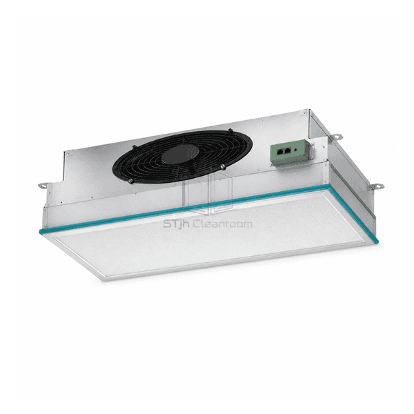
The EC fan filter unit brings the blower, electronic motor drive and final filter together in a modular clean-air assembly. Electronic commutation replaces mechanical brushes, while the drive regulates fan speed. This arrangement is useful where ceiling units need to be balanced individually or adjusted as a group. The control package, filter frame and service layout determine how the unit connects to the wider cleanroom installation.
Electronic commutation avoids brush replacement as a routine motor maintenance task.
Motor-speed regulation allows the airflow setting to be matched to the installed filter and air path.
The specified interface can support local operation or integration with a compatible facility controller.
For an EC FFU array, the useful questions are how each unit is adjusted, what feedback is available and how the selected duty is verified.
Common EC ceiling-module references with independently selectable filtration and motor-control interfaces.
| Unit Type | Motorized final-filter module for cleanroom air supply |
|---|---|
| Motor Technology | Electronically commutated brushless drive |
| Common Module Formats | Nominal 600 × 600 mm or 600 × 1200 mm ceiling modules |
| Typical Unit Height | Approximately 250–380 mm for conventional EC ceiling FFU assemblies |
| Common Mains Supply Options | 220–240 V AC, single phase, with 50 Hz or 60 Hz versions |
| Housing Options | Aluminium, powder-coated steel or stainless-steel casing |
| Airflow Adjustment | Electronic motor-speed regulation |
| Filtration Arrangement | Fan and replaceable final-filter assembly in one module |
| Filter Options | H13/H14 HEPA or U15 ULPA filter configurations |
| Control Interface Options | Local potentiometer, 0–10 V speed-command input or Modbus RTU network control, according to controller version |
| Service Options | Top-side motor access or room-side service configurations for the filter, motor and controller |
| Penyesuaian | Boleh didapati berdasarkan aplikasi yang dimaksudkan dan persekitaran operasi. |
Configuration choices include local or remote speed adjustment, compatible network controls, final-filter selection and top-side or room-side servicing. Availability depends on the selected motor, controller and housing arrangement; these choices are not all included in a base EC unit.
Specify required airflow in m³/h together with the external static pressure in Pa, the selected filter and its initial resistance. Allow for the additional resistance expected as the filter loads. An EC motor or a speed command alone does not provide automatic constant-airflow control. Where that function is needed, include the sensor, control loop and operating limits in the equipment scope.
The low-voltage speed signal is not the motor power supply. Obtain the unit input voltage, frequency, running current, starting characteristics and power at the selected duty before sizing circuits. Select local adjustment, an analog input or network control to suit the facility. A networked arrangement also needs an agreed protocol, addressing method, cable topology and defined status or alarm signals. Motor-speed feedback is not a direct airflow measurement.
Check overall length, width and height in mm, ceiling opening, support points, weight and unobstructed inlet clearance. Decide whether the filter, fan and controller will be accessed from above or from the room; access to one component does not establish access to all three. Isolate the electrical supply before service and protect the filter face and perimeter seal during installation.
The EC designation identifies the drive technology. It does not by itself include a supervisory controller, network cabling, airflow sensor, ULPA filter, duct collar or room-side service arrangement. List the selected filter, seal, control equipment and accessories separately in the quotation. Compare the AC fan filter unit when a different drive arrangement is preferred, or the low-profile fan filter unit when ceiling height is the main constraint.
Hantarkan kepada kami dimensi anda, syarat pemasangan, sasaran prestasi dan kemasan permukaan yang diperlukan.