
 영어
 포르투갈어
 스페인어
 말레이어
 인도네시아어
 독일어
 터키어
 베트남어
 프랑스어
 러시아어
 아랍어
 태국어
 일본어
 한국어현재 Current


상품 소개
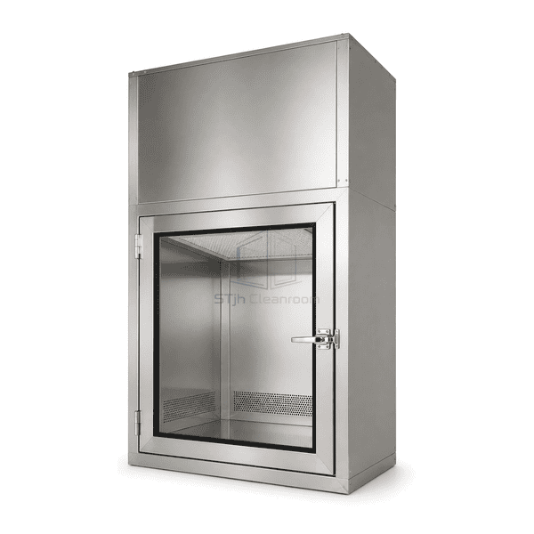
The vertical unidirectional-flow pass box places the final filter above the transfer space and carries returning air towards lower passages. A fan supplies the upper plenum, while the perforated support and side openings form the chamber's return route. This is a directed-flow arrangement for suitably positioned components, distinct from a cabinet that merely recirculates filtered air and from a material shower using concentrated cleaning jets.
주요 기능
Lower return passages keep collection points away from the upper supply face.
A removable perforated support provides access to the surface below it.
Adjustable fan control allows air-speed settings to be matched to the selected filter.
A local airflow readout makes changes in operating condition visible.
응용 프로그램 솔루션
The important purchasing question is whether the proposed chamber remains useful with the real transfer load in place.
A wide tray blocks the air path below the filter.Select the chamber and loading clearance around that tray, keeping its edges away from return openings rather than assuming a larger blower removes the obstruction.
Residue collects beneath a fixed solid support.Choose a lift-out perforated shelf and accessible lower surfaces so routine wiping can reach those areas.
Filter resistance changes while the same fan setting is retained.Use the selected velocity and pressure indications to distinguish an airflow change from a door or filter-maintenance problem.
The receiving door becomes available immediately after a disruptive loading step.Choose a release sequence that allows the required airflow restoration interval, with its suitability evaluated for the actual payload and transfer routine.
일반적인 응용 프로그램
Clean optical component traysElectronics assembly carriersPharmaceutical process containersLaboratory supply transfer
Use this configuration for materials that benefit from a controlled downward air path. A HEPA filter and directional airflow do not establish sterility, a room cleanliness class, or personnel and environmental containment for hazardous substances.
기술 매개변수
The following are common selectable construction and airflow references for this vertical-flow arrangement, not an as-built STjh performance schedule. Air speed is a measuring-plane selection; it does not establish uniform flow around every loaded object, chamber classification or recovery time.
| 기류 배치 | Ceiling final-filter supply with downward chamber flow and low-level return passages |
|---|---|
| 챔버 재질 | SUS 304 스테인리스강 |
| Common Internal Size References | 500 × 500 × 500 mm or 600 × 600 × 600 mm, W × D × H |
| Stainless Sheet Reference | 1.2 mm nominal sheet |
| Air-Speed Selection Reference | Nominal 0.45 m/s at the selected measuring plane |
| 여과 단계 | Prefilter followed by a ceiling-mounted HEPA final filter |
| Load Support | Perforated support surface with lower side-return openings |
| Transfer Doors | Two gasketed doors with electronic interlocking |
| Airflow Indication | Velocity indication; differential-pressure monitoring available |
| Electrical Supply References | 220 V AC; 50 Hz or 60 Hz equipment variants |
| Cleaning Jet Circuit | No high-velocity air-shower nozzle circuit |
| 사용자 정의 | 의도된 응용 프로그램 및 운영 환경에 따라 사용할 수 있습니다. |
사용 가능한 옵션
Gel-seal filter mounting차동 압력 디스플레이Separate air-velocity sensorEC fan controlAdjustable shelf positionIntercom and transfer-status alarms
The base arrangement is the ceiling supply, return passages, load support and interlocked doors. Filter sealing, motor type, measuring hardware and added communication functions are individual selections; they are not all implied standard equipment.
Selection and Installation
Choose the air path around the actual load
A vertical-flow cabinet is selected for the direction and distribution of its air, not simply because a fan is installed. Show the largest tray, container height and loading position when choosing the chamber. A broad object beneath the ceiling filter creates a wake; leave appropriate clearance to the filter face and return openings. A perforated shelf does not make the underside of an opaque container directly exposed to clean supply air.
Separate velocity from delivered performance
State where the air-speed target will be measured and whether the chamber is empty or loaded. Fan adjustment can change flow, but it cannot by itself demonstrate an undisturbed downward pattern, a specified particle-recovery interval or an aseptic transfer result. Match the filter area and return geometry before selecting the blower. Keep fan power, sound level and pressure rise tied to that same offered assembly rather than combining catalogue figures.
Identify services and access
This arrangement includes a fan-filter supply and return path. A facility-fed alternative needs its own inlet, return or exhaust arrangement; it is not interchangeable with the recirculating chamber merely by adding a duct connection. Allow access to the final filter, prefilter, fan and measuring points, and retain sufficient wall support and door-swing space.
Set the transfer sequence
Define loading, door closure, airflow restoration and receiving-side release for the intended materials. A timed delay is a control setting rather than proof that a contamination endpoint has been reached. For packages requiring directed surface de-dusting instead of a broad downward sweep, compare the material air-shower pass box.
수직 단방향 흐름 패스 박스 사양을 계획하고 있습니까?
치수, 설치 조건, 성능 목표 및 필요한 표면 마감을 보내십시오.