Airflow zoning by panel selection
Different perforation patterns can be placed where room airflow demand differs, avoiding the assumption that every location should receive the maximum possible opening area.

 Bahasa Inggeris
 Bahasa Jerman
 Bahasa Arab (Bahasa Melayu)
 Bahasa Perancis
 Bahasa Indonesia: Bahasa Indonesia
 Bahasa Jepun
 Bahasa Korea (Bahasa Melayu)
 Bahasa Melayu (Bahasa Melayu)Semasa
 Bahasa Portugis: Bahasa Portugis: Bahasa Portugis
 Bahasa Rusia
 Bahasa Sepanyol: Bahasa Sepanyol: Bahasa Sepanyol
 Bahasa Melayu (Bahasa Melayu)
 Bahasa Turki: Bahasa Turki
 Bahasa Vietnam (Bahasa Melayu)

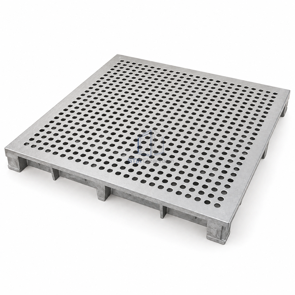
The AV45 configuration combines an orthotropic die-cast aluminum body with a selected perforation pattern. Available free areas span approximately 3.6–45%, allowing the floor layout to distribute air according to the room's equipment arrangement. The 600 mm grid aligns with compatible solid modules. Changing the open area changes the ventilation geometry and must be considered alongside the load-bearing variant.
Different perforation patterns can be placed where room airflow demand differs, avoiding the assumption that every location should receive the maximum possible opening area.
The ribbed aluminum structure carries the perforated face. Hole patterns and structural geometry belong to the same selected panel, not an arbitrary site-drilled modification.
Compatible modules allow the ventilation layout to evolve with equipment positions. Rebalancing remains necessary when floor panels or process tools are moved.
| Panel Grid | 600 x 600 mm |
|---|---|
| Panel Thickness Range | 52–60 mm |
| Body Material | Die-cast aluminum |
| Structural Geometry | Orthotropic |
| Free-Area Range | Approximately 3.6–45% |
| Top Construction | Factory-selected perforations |
| Support System | Height-adjustable pedestal arrangement |
| Kemasan permukaan | Suitable conductive or non-conductive finish |
| Ventilation Role | Cleanroom recirculation path |
| Penyesuaian | Boleh didapati berdasarkan aplikasi yang dimaksudkan dan persekitaran operasi. |
Use in cleanrooms where recirculation paths need to follow changing process layouts. Open area is a geometric value, not a guaranteed air volume: the pressure difference, available plenum space and obstructions influence actual flow. Keep tool bases and cable bundles from blocking selected openings after the floor has been balanced.
Select perforation patterns by zone and measure room performance with the final equipment arrangement in place.
Review panel positions and underfloor obstructions, then rebalance the affected zones rather than assuming the previous layout remains suitable.
Choose a supported perforation pattern, panel depth and finish. Identify solid-panel locations and service openings together with the ventilation plan so later equipment changes do not undermine floor support or airflow distribution.
Hantarkan kepada kami dimensi anda, syarat pemasangan, sasaran prestasi dan kemasan permukaan yang diperlukan.